@Wuerfel_21 said:
Ah, I see, that's what's going on with the USB connector. They designed it to plug into the Pi Zero. Yeah that's just doing OTG, which should work passively if you're just trying to be a host. I think an actual OTG device needs that extra 5th pin to do something to switch into host mode, but we just assume we're a host (and I think the Pi Zero does, too? I don't think it can do device mode?) So trying it with the Serial Device accessory is fine if you can manage that.
You're saying this USB connector doesn't have GND and VBUS connected to anything? That'd be odd.
Yeah they both float, only D-/D+ pass through the flex cable to the card edge fingers. I guess the controller doesn't really need ground and VBUS because it's supplied internally and grounded separately. 5V already directly powers the Pi from the Case 2W Lipo boost converter, so there's really no need to feed 5V back via VBUS into the controller with the Pi acting as a host..even though normally the Pi would want to power the device being plugged into its OTG port.
The fifth ID pin thing I believe is just a way to identify which end of the OTG cable A or B is plugged into the port so it knows what to default to at startup, although there are more advanced protocols nowadays that can control a lot of that. I am hoping this USB controller is kinda dumb and not too smart for it's own good so it will interwork with your driver. https://en.wikipedia.org/wiki/USB_On-The-Go
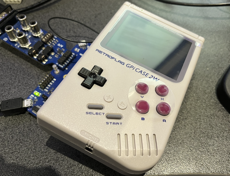
Don't want to put the cart before the horse but if initial testing works out we might be able to make a 64MB PSRAM P2 board that fits neatly inside the cartridge...and could look a bit like this. Maybe HDMI out is an option as well (micro or mini socket). Or if we can figure out USB-C alternate modes we could dual purpose that instead for carrying HDMI and/or a PropPlug input path via USB.
UPDATE: we could do something like this perhaps...
P0 - uSD card power reset/detect pin?
P1 - PSRAMCS1
P2 - PSRAMCS2
P3 - PSRAMCLK1
P4 - PSRAMCLK2
P5 - LCD VSYNC
P6 - LCD HSYNC
P7 - LCD DE
P8,9 - USB D-/D+
P10-15 - BLUE
P16,17 - PWM1, PWM2
P18-23 - GREEN
P24,25 - POWERON, !POWERDOWN
P26-P31 - RED
P32-P39 - HDMI
P40-P55 - PSRAM DATA
P56 - LCD PIXELCLK
P57 - independent uSD card DO pin or !CS to interfere less with boot Flash?
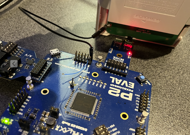
Looking good for USB. I just hooked up a janky connection to the handheld case via the Parallax serial device breakout on a P2-EVAL and a separate ground wire and loaded USBNEW's hidpad_to_vga.binary application. Am now seeing all front buttons (except the turbo "star" which I think only acts locally inside the controller to turbo press a nominated switch in-game), report binary 1 when pressed, also including the rear trigger switches and extra "home" switch on the front panel which can be used to jump out to a menu. The 4 way direction switch reports as a HAT with values from 00-07 or 0F depending on which direction(s) are actively pressed down on the 8 way switch. The USB PID/VID reports this as an XBOX360 controller.
This is great news so far. I didn't do a lot of experimenting with P2 resets and shutdowns etc, but so far so good and means really it's just the LCD that needs to work now for this to be a success. I do hope it's not flipped or something, then we might be screwed.
Tried feeding a P2 OPN2 cog demo audio output into the GPi Case 2W's GPIO19 pogo pin position (which should be one of the audio PWM channel inputs) with the unit switched on but couldn't hear anything with volume level slid fully up/down. Might be a couple of things. Perhaps the internal amp path is only turned on when active video is present, to avoid clicks/pops at startup, or perhaps P2 DAC line level outputs are no good and PWM logic levels are needed if filtered/processed internally. Harder to reach GPIO18, but that might also be it if it uses a mono amp only internally - I should retry this from the headphone outputs too. EDIT: no output on headphone socket L&R either.
Hmm, digitally buffering the PWM signal would be A Choice, certainly.
I think I can add PWM audio as an option (I think this just requires changing some values), but the quality will be really low, since each sample period is only a few thousand cycles (so 12 to 13 bit quality?). OPN2cog is special in that it actually runs comically high sample rates (so ~1/6th of normal sample period!), but only has 9 bits of effective output precision to begin with, so shrug.
But more likely the amp circuit just isn't enabled and needs to be started somehow.
Says 600 mA at 5V, but guess that's not enough. Or, being pulled under 5V so that USB doesn't work.
Think the solution here is to power the SWaP directly from lipo and use the boosted 5V only for USB.
Also, made a mistake with power switch. Was originally targeting a different module that needed a momentary switch, but this booster board needs an actual on-off switch that can handle the full current...
But, for now can just power using small power bank.
Main issue now is the uSD not working unless accessed first by FSRW.
Have to either mod Megayume and add some FSRW code, or come up with a menu program that can boot a binary file from uSD.
Seems will want a menu at some point anyway, so guess will go that way...
Need to look at either the @Wuerfel_21 teapot code or think there was a suggestion of using Megayume upper.
@Rayman said:
Says 600 mA at 5V, but guess that's not enough. Or, being pulled under 5V so that USB doesn't work.
That should be fine even if it's kinda thinning the soup. It appears the P2 EDGE running MegaYume + the 2" LCD together consume ~360mA at 5V. (no idea if the SWaP board is more or less efficient). Though if that USB controller consumes more than ~100mA you might start getting into problems. Though all the ones I've tried read as zero on the meter (again, cursed USB amp meter, maybe try this yourself - you probably want to not have > 500mA average current if you want the battery to actually last).
Think the solution here is to power the SWaP directly from lipo and use the boosted 5V only for USB.
I don't you're supposed to do that, the battery needs a protection thing on it?
@Rayman said:
But, for now can just power using small power bank.
Main issue now is the uSD not working unless accessed first by FSRW.
That should hopefully be fixable...
Have to either mod Megayume and add some FSRW code, or come up with a menu program that can boot a binary file from uSD.
Seems will want a menu at some point anyway, so guess will go that way...
Need to look at either the @Wuerfel_21 teapot code or think there was a suggestion of using Megayume upper.
Don't look at the teapot, that has nothing useful for this. Re-using the megayume menu code might be a bit trickier than I implied then, because to actually show anything it needs the whole VDP thing set up and running, which is a bit involved.
Maybe I should just make it myself, after all.
@rogloh said:
Don't want to put the cart before the horse but if initial testing works out we might be able to make a 64MB PSRAM P2 board that fits neatly inside the cartridge...and could look a bit like this. Maybe HDMI out is an option as well (micro or mini socket). Or if we can figure out USB-C alternate modes we could dual purpose that instead for carrying HDMI and/or a PropPlug input path via USB.
UPDATE: we could do something like this perhaps...
P0 - uSD card power reset/detect pin?
P1 - PSRAMCS1
P2 - PSRAMCS2
P3 - PSRAMCLK1
P4 - PSRAMCLK2
P5 - LCD VSYNC
P6 - LCD HSYNC
P7 - LCD DE
P8,9 - USB D-/D+
P10-15 - BLUE
P16,17 - PWM1, PWM2
P18-23 - GREEN
P24,25 - POWERON, !POWERDOWN
P26-P31 - RED
P32-P39 - HDMI
P40-P55 - PSRAM DATA
P56 - LCD PIXELCLK
P57 - independent uSD card DO pin or !CS to interfere less with boot Flash?
Oh, I didn't see this one before~
So, uh HDMI+LCD simultaneous isn't happening (hardware limit) and the code I have really is not designed to switch outputs at runtime (especially not from/to HDMI with its massive TERC encoder overlay).
Doing VGA+LCD could work, but that REALLY wants the LCD's HSYNC to be on P0.
For USB video, you really need DisplayPort signalling (the HDMI alt mode AFAIK only exists on paper), which is a whole other can of horrible worms. Apparently there used to be a DP encoder that'd have fit the bill (STDP4028) but of course useful parts get the axe. Maybe a tiny FPGA could that trick, but that'd require a bunch of severely annoying programming.
So in that light, maybe better idea to just do 4bit SD there.
Also, how do those soft power control pins work? I think this can be made to work nicely with very little code (though in for a bad time if you ever get a hang).
Second thought: Though if the 640x480 display used is anything like the ones I can find, the controllers are designed for somewhat higher resolutions, so shouldn't mind being clocked slightly too fast.
In that case you could include some TFP401-shaped device to drive the parallel interface from our HDMI output, which then just needs to be buffered somehow so it can go to two sinks. Didn't you already make a breakout for that chip, @rogloh ?
Oh wow you got that to show graphics beyond the tile font? Or just replaced the graphics bit wholesale?
Was starting to think about how I'd make one (overcomplicated, as usual... I think a good loader should invoke the kind of vibe the PlayStation 2 OSDSYS has, maybe can leave those ideas cooking longer...
Should really sooner work instead on getting more executables that can be loaded ready. I.e. fix up Spin Hexagon and get that collection of P1 ports released (currently only 3 games, but can add more over time I guess.)
@Rayman if you want to place the mailbox in high memory, you need to
Remove the exmem_mailbox VAR declaration
add something like #define exmem_mailbox long[$7F000] near the top
clear the mailboxes somewhere at beginning of the initialization
Also, I think you have some random addresses still going around. That's my fault, I didn't mark them out. E.g. the $F8 in the video driver init is an address that holds... something, I think the line counter? This will trash your code if it's not moved to upper memory like it originally was. These should be something like @linectr (which needs to be defined in the VAR section)
Unrelatedly, y'all can feel free to beta-test the aforementioned game port library, I have published it: https://git.sr.ht/~wuerfel_21/p2gameports (trying to upload that one to sourcehut exclusively for now as some sort of CIA experiment to figure out if people understand how to do a git clone off that - I elaborated elsewhere but frick Micro$soft, I'm getting off the GitHub ride). Last I checked the LCD6 support in this worked. 🔑Jingles keys🗝️ This has a video driver that does 8bpp indexed, btw (to re-create the P1 NTSC palette)
@Wuerfel_21 said:
So, uh HDMI+LCD simultaneous isn't happening (hardware limit) and the code I have really is not designed to switch outputs at runtime (especially not from/to HDMI with its massive TERC encoder overlay).
Yep I already gathered that. You could only really do DAC VGA and HDMI (or parallel LCD) unless you have another free COG. It'd be one or the other type of output.
Doing VGA+LCD could work, but that REALLY wants the LCD's HSYNC to be on P0.
That could always be done if necessary, but HDMI out is better than VGA and it can carry audio. Whether or not it's achieved via USB-C or a mini/micro connector is a separate decision. Plus there are no common low profile solutions for VGA.
For USB video, you really need DisplayPort signalling (the HDMI alt mode AFAIK only exists on paper), which is a whole other can of horrible worms. Apparently there used to be a DP encoder that'd have fit the bill (STDP4028) but of course useful parts get the axe. Maybe a tiny FPGA could that trick, but that'd require a bunch of severely annoying programming.
Yeah I read that there aren't really any USB-C to HDMI alternate mode devices even though the HDMI signals in that mode are specified on the connector but I yet do see cheap (passive?) USB-C to HDMI cables for sale so not 100% sure what gives there.
Also, how do those soft power control pins work? I think this can be made to work nicely with very little code (though in for a bad time if you ever get a hang).
I am yet to probe it all it out but it can't be difficult based on the RasPi scripts. It seems one pin is an input and the code looks for a falling edge before shutting down another pin which it normally pulls high at startup. This soft-shutdown feature is selectable via a tiny slide switch under the cartridge slot as opposed to the main switch which also locks the cartridge - so you can't yank it out while switched on and running. With the soft shutdown feature disabled the 5V power out to the edge connector get switched on/off when the main slide switch at the top is on/off. Haven't tried it in the other position yet. Sort of want a real FireAnt test board back before checking these things too much further, as probing the pogo pins within the case is a little tricky and prone to shorting adjacent pins if you are not extra careful. If it ever hung yeah then you'd need to pull the cartridge and put it back. There is an LED that lights when on so at least you'd know if it didn't shutdown.
Didn't you already make a breakout for that chip, @rogloh ?
Yeah I did make a breakout for the TFP401, that's the blue ringed octopus board I made. Not sure it could fit on a FireAnt's PCB size or inside the cartridge. It has a lot of signals on that device. You'd likely need a separate board above and an interconnect to achieve that IMO.
Video stuff is all very unfortunate. Why is everything so inaccessible now? It seems hobbyists only get stuff that is ~15 years behind the curve at any given moment.
For analog video, there is a common low-profile connector, the humble 3.5mm TRRS can either do composite+audio or YPbPr. Composite is out because different scan rate. And big poopy problem is that the P2 can not do soggy formats at the same time as TMDS due to disagreement on DAC0 usage. What would be possible is to output YUV+CSync and then use a transistor or something to pull Y down externally for the sync period.
Though I think even the component video jacks are disappearing nowadays.
Also, how do those soft power control pins work? I think this can be made to work nicely with very little code (though in for a bad time if you ever get a hang).
I am yet to probe it all it out but it can't be difficult based on the RasPi scripts. It seems one pin is an input and the code looks for a falling edge before shutting down another pin which it normally pulls high at startup. This soft-shutdown feature is selectable via a tiny slide switch under the cartridge slot as opposed to the main switch which also locks the cartridge - so you can't yank it out while switched on and running. With the soft shutdown feature disabled the 5V power out to the edge connector get switched on/off when the main slide switch at the top is on/off. Haven't tried it in the other position yet. Sort of want a real FireAnt test board back before checking these things too much further, as probing the pogo pins within the case is a little tricky and prone to shorting adjacent pins if you are not extra careful. If it ever hung yeah then you'd need to pull the cartridge and put it back. There is an LED that lights when on so at least you'd know if it didn't shutdown.
Yeah, I checked it, so what I gather is
POWERON gets set high when the processor is done booting
if !POWEROFF goes low, the processor shuts down and thereby releases POWERON
the actual power then presumably gets cut?
I think that can be integrated into P2 software fairly easily, could maybe rig up a simple library. This would also handle "soft reset" capability (i.e. to quit back to a loader). NeoYume is tricky because there's no cog running Spin code, but that also doesn't do anything that cutting the power would get in the way of, maybe sneak it into the VBlank code for one of the video cogs.
Didn't you already make a breakout for that chip, @rogloh ?
Yeah I did make a breakout for the TFP401, that's the blue ringed octopus board I made. Not sure it could fit on a FireAnt's PCB size or inside the cartridge. It has a lot of signals on that device. You'd likely need a separate board above and an interconnect to achieve that IMO.
Chip Too Big, the classic problem.
@Wuerfel_21 said:
Unrelatedly, y'all can feel free to beta-test the aforementioned game port library, I have published it: https://git.sr.ht/~wuerfel_21/p2gameports (trying to upload that one to sourcehut exclusively for now as some sort of CIA experiment to figure out if people understand how to do a git clone off that - I elaborated elsewhere but frick Micro$soft, I'm getting off the GitHub ride). Last I checked the LCD6 support in this worked. 🔑Jingles keys🗝️ This has a video driver that does 8bpp indexed, btw (to re-create the P1 NTSC palette)
BTW if anyone tried this yet and the shell script faceplanted trying to build Unterwelt, it is fixed now. I forgot that last time I was working on this I was waiting on an upstream fix for a really dumb problem so I changed the script to take the compiler from my dev directory
I am also running into even more strange issues now, so proper release may be delayed.
Added this fsrw code to MegaYume Upper and now can boot into Megayume and work:
    'Try to mount a few times then give up if not successful
    repeat 10
        waitms(500)
        x:=sd.mount_explicit(MISO, CLK, MOSI, CS)
        if x<0

          sd.release() 'see if this helps next attempt
        else
            quit 'escape from repeat loop if mounted
    sd.release()
@Wuerfel_21 said:
I think that can be integrated into P2 software fairly easily, could maybe rig up a simple library. This would also handle "soft reset" capability (i.e. to quit back to a loader). NeoYume is tricky because there's no cog running Spin code, but that also doesn't do anything that cutting the power would get in the way of, maybe sneak it into the VBlank code for one of the video cogs.
That'd be neat if possible. Especially if the "home" key could be pressed dropping us back to the top game menu, restarting the P2 when necessary for that. That'd make a self contained handheld as is being discussed quite usable, particularly with a fast flash based boot which might be sub-second with any luck. Otherwise SD boot is a bit clunky for my liking.
UPDATE: just probed power control signals when the soft power switch mode is enabled. But I'm seeing strange results. The POWEREN pin (unpowered) rises to 600mV when probed (floating logic input?). POWEROFF pin is seen briefly at logic high then rapidly drops to around 1.5V when probed which seems a strange so not sure what logic is running there - this of course was with the cartridge not fitted so it may not operate the regular power control logic the same way in that state. That test was done with the main top slide switch in the on position. When I slid the main switch off I do see the POWEROFF pin quickly drop low and the power did turn off according to the LED and probed 5V output. I think I'll need to wait for a real P2 attached to experiment further or somehow probe a real RasPi operating in this handheld case.
@Wuerfel_21 said:
I think that can be integrated into P2 software fairly easily, could maybe rig up a simple library. This would also handle "soft reset" capability (i.e. to quit back to a loader). NeoYume is tricky because there's no cog running Spin code, but that also doesn't do anything that cutting the power would get in the way of, maybe sneak it into the VBlank code for one of the video cogs.
That'd be neat if possible. Especially if the "home" key could be pressed dropping us back to the top game menu, restarting the P2 when necessary for that. That'd make a self contained handheld as is being discussed quite usable, particularly with a fast flash based boot which might be sub-second with any luck. Otherwise SD boot is a bit clunky for my liking.
You can get SD boot pretty quick if you use the fast boot stub + a compressed executable. Though always janky to just get nothing if/when the boot fails. So flash is better in that sense.
Lots of controllers have a home key, so it'd be good to be able use it like that. Should probably have to hold it for a bit, since the loader can't just restore back into the game like a real OS could and trying to add a GUI HOME menu for this into every executable, Wii-style, is not feasible due to graphics technology diversity. Though ctrl+alt+del on keyboard could be instant.
Trying to think what the soft shutdown library would look like from the outside. It should be as drop-in as possible. Needs 3 functions, one init function, one called periodically (every frame or so) to check if shutdown is needed and finally one to actually shut down.
Something like
OBJ foo : "foo.bar" | some parameters idk
PUB main
foo.init()
_mount(something)
repeat
  if foo.should_shutdown()
    _umount(something)
    foo.do_shutdown()
Big question is what is ideal to grab gamepad/keyboard data for soft reset. Probably bad idea to tie it to usbnew too hard. Also can't read the xbox home button through emupad currently (with default map). Maybe usbnew can be tied to the library (i.e. add a new special sauce function to grab home and ctrl+alt+del)
Incidentally, the state of things you could possibly load right now, AFAIK:
Software
Type
Build/config
Compiler
Ext. RAM
Storage
HDMI audio
LCD support
Uses usbnew
Note
MegaYume
Emulator
Medium
flexspin
PSRAM+Hyper
SD (flexC)
Yes
Yes
Yes (hacked version)
NeoYume
Emulator
Medium
flexspin
PSRAM+Hyper
SD (flexC) / 4bit (SDSD)
Yes
Yes
Yes
MisoYume
Emulator
Medium
flexspin
PSRAM+Hyper
SD (flexC)
Yes
Yes (bad for H512)
Yes
beta-quality software
RAM test
Utility
Medium
flexspin
PSRAM+Hyper
N/A
Yes
Yes(?)
N/A
Shares NeoVGA driver
Spin Hexagon (P2 ver.)
Game
Easy?
flexspin
N/A
SD (custom driver)
NO
NO
Yes
Uses @rogloh video driver.
Tempest 2000
Game
HARD-ish
flexspin (bundled)
PSRAM+Hyper
SD (flexC) or flash (PFS) or 9P
Yes
Yes
Yes
video-nextgen branch
@macca 's Atari 2600 emulator
Emulator
Easy?
Spin Tools
N/A
ROMs compiled into binary
NO
NO
Yes (hacked version)
There's more of these to consider
P1 Classics Collection
Games, plural
Easy
flexspin
N/A
SD (flexC, optional)
Yes
Yes
Yes
Beta, not propely announced yet
If I forgot something sufficiently funny, please enlighten me. I mostly remember my own nonsense.
For p1 classics collection I currently have 3 games (Unterwelt, Ranquest and Spintris) + 2 more I'm working on (PropICE -> waiting on upstream @ersmith bugfix, IMPACT -> need to rework some input stuff still). I think I'll do another 1 or 2 and then work on polish before I publish it with a full thread and all.
These all use a common HAL with video/input/FS stuff taken care of. They run at ~250 MHz and need no PSRAM or other fancy shmancy stuff.
That's a fairly comprehensive and impressive list now @Wuerfel_21 . It'd be neat to have a way to switch between (say) the first 3 emulators on common hardware with PSRAM and USB controllers and not need to reprogram the whole device with a new P2 emulator (esp. for standalone/portable use). Given the flash is typically able to hold up to 16MB, maybe some small top level menu app that runs first could then secondary load the actual emulator application from another area of flash, or instead have some way to change the default emulator by holding another controller key down at reboot perhaps as you also press/hold the home button. Having a top level emulator choice menu would be somewhat like what happens on the RasPi emulators too.
I realize that this could complicate the overall build process to setup the flash image correctly with the different emulators and could take a bit of figuring out how to load it all up.
@rogloh said:
That's a fairly comprehensive and impressive list now @Wuerfel_21 . It'd be neat to have a way to switch between (say) the first 3 emulators on common hardware with PSRAM and USB controllers and not need to reprogram the whole device with a new P2 emulator (esp. for standalone/portable use). Given the flash is typically able to hold up to 16MB, maybe some small top level menu app that runs first could then secondary load the actual emulator application from another area of flash, or instead have some way to change the default emulator by holding another controller key down at reboot perhaps as you also press/hold the home button. Having a top level emulator choice menu would be somewhat like what happens on the RasPi emulators too.
I was always thinking SD loading, because you need that for bulk storage, anyways (see table), but flash would also work. That has the advantage that you can't fumble the cards between boards and end up launching apps compiled for the wrong hardware.
16MB is plenty to fit the main executable of a lot of software.
Incomplete, kinda non-scientific table:
Software
Binary size
MegaYume
95580
NeoYume
72509
MisoYume
71635
SpinHexagon
47845
Tempest 2000
65756
Unterwelt (P1CC)
87819
Spintris (P1CC)
44871
Ranquest (P1CC)
63905
This all with the usual LZ4 self-compression applied. Note that for SpinHexagon, the current build script doesn't have compression enabled, but I did here for better comparsion.
Interesting observation is that the plain P1 ports (Spintris, Hexagon) both grow to ~48K on the P2. (Unterwelt and Ranquest had their EEPROM/SD extra data included into the exe, which skews the result). I blame the flexspin libc bloat (which also makes up large portions of the emulator binaries).
On a related thing, do note that nothing stops you from just listing the ROM files in a loader and in a sense abstract away the underlying emulator - that's what the ARGv mechanism is for.
I realize that this could complicate the overall build process to setup the flash image correctly with the different emulators and could take a bit of figuring out how to load it all up.
I did try to make a tool that creates PFS images "offline" once, but could never get it to work properly. Might need to try again. Loading it up should be easy, loadp2 can just flash large files to high memory. Though IDK if it can easily erase the unused sectors.
Making a script that auto-builds all the apps is also a TODO item.
(Another thing I really want to get to is fixing the MisoYume DMA and timing problems - still no Secret of Mana, I am being deprived~)
@Rayman said:
Logicon survived first day at middle school…
Seems getting more games is top of list now…
@rogloh said:
Nice one @Rayman, we don't need some high-handed wannabe adjutant confiscating an important software test platform, do we.
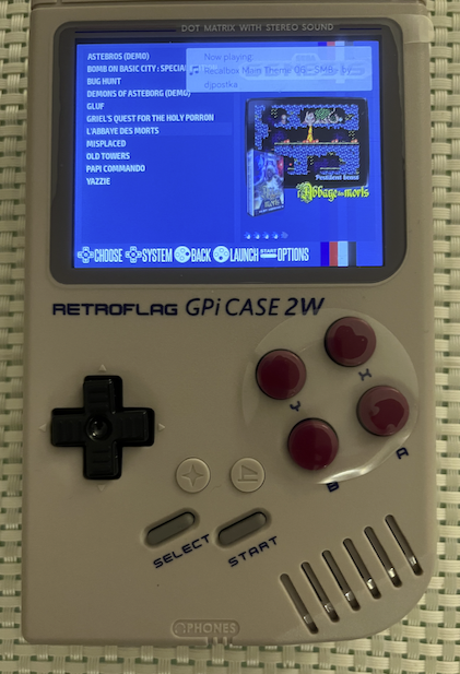
Just did some validation that the LCD HW works by using a RasPi Zero in this case running Recalbox. Am seeing a valid screen now after a bit of mucking around with the Pi boot configuration (documentation I found online doesn't seem to work). I also had audio output working at one point but now it is not again . Seems to be an issue related to a mix of old/new config parameters used by different software versions etc. But I'm confident the HW I have at least can be made to work now.
@Wuerfel_21 said:
Oh good. Might try to rig up some sound program with PWM output for testing purposes (if it's a really a TTL level thing...)
The GPIO pins on a Pi can only really output as LVCMOS/TTL and they aren't DACs to my knowledge. They do talk about some advanced PWM output format, selected as audio_pwm_mode=2. I read that "This enables the sigma-delta oversampled PWM with ~16-bit resolution."
One other thing I think I can try in the meantime is to mess about with the video timing using the RasPi to test VGA resolutions etc.
There's a configuration setting which lets you select timing using this format, whose parameters are listed below hdmi_timings=640 0 1 1 20 480 0 1 1 2 0 0 0 60 0 32000000 1
Name Description/ Unit
Horizontal active pixels
Horizontal sync polarity 0: Low active/ 1: High active
Horizontal front porch cycles
Horizontal sync width cycles
Horizontal back porch cycles
Vertical active lines
Vertical sync polarity 0: Low active/ 1: High active
@Wuerfel_21 said:
Oh good. Might try to rig up some sound program with PWM output for testing purposes (if it's a really a TTL level thing...)
The GPIO pins on a Pi can only really output as LVCMOS/TTL and they aren't DACs to my knowledge. They do talk about some advanced PWM output format, selected as audio_pwm_mode=2. I read that "This enables the sigma-delta oversampled PWM with ~16-bit resolution."
Yeah I know. The question was wether the case accepts regular line-level audio or if it needs TTL signals.
One other thing I think I can try in the meantime is to mess about with the video timing using the RasPi to test VGA resolutions etc.
There's a configuration setting which lets you select timing using this format, whose parameters are listed below hdmi_timings=640 0 1 1 20 480 0 1 1 2 0 0 0 60 0 32000000 1
That seems incorrect, that would actually come out at ~100Hz
@Wuerfel_21 said:
Oh good. Might try to rig up some sound program with PWM output for testing purposes (if it's a really a TTL level thing...)
The GPIO pins on a Pi can only really output as LVCMOS/TTL and they aren't DACs to my knowledge. They do talk about some advanced PWM output format, selected as audio_pwm_mode=2. I read that "This enables the sigma-delta oversampled PWM with ~16-bit resolution."
Yeah I know. The question was wether the case accepts regular line-level audio or if it needs TTL signals.
Still to determine that. It probably has an RC low pass filter since there isn't one on the Pi Zero vs other models but whether it's buffered first, not sure yet. I believe they do buffer it in the audio circuits on the Pi 3, 4 etc.
One other thing I think I can try in the meantime is to mess about with the video timing using the RasPi to test VGA resolutions etc.
There's a configuration setting which lets you select timing using this format, whose parameters are listed below hdmi_timings=640 0 1 1 20 480 0 1 1 2 0 0 0 60 0 32000000 1
That seems incorrect, that would actually come out at ~100Hz
Yeah that's a bad example I'd copied. Another one I found with the same pixel & line count used 19.2Mhz for 60Hz. I'm finding a lot of misinformation online regarding this stuff unfortunately, or at least conflicting stuff - could be version related.
Update: just got sound back using dtoverlay=audremap,pins_18_19,swap_lr
LOL this thing has got ports of Doom and Prince of Persia on it, I'm set!
I'd be doing modes with much more blanking, but it should be able to handle that. Might configure for /12 pixel clock divider and then adjust the H timings on that basis.


Comments
Yeah they both float, only D-/D+ pass through the flex cable to the card edge fingers. I guess the controller doesn't really need ground and VBUS because it's supplied internally and grounded separately. 5V already directly powers the Pi from the Case 2W Lipo boost converter, so there's really no need to feed 5V back via VBUS into the controller with the Pi acting as a host..even though normally the Pi would want to power the device being plugged into its OTG port.
The fifth ID pin thing I believe is just a way to identify which end of the OTG cable A or B is plugged into the port so it knows what to default to at startup, although there are more advanced protocols nowadays that can control a lot of that. I am hoping this USB controller is kinda dumb and not too smart for it's own good so it will interwork with your driver. https://en.wikipedia.org/wiki/USB_On-The-Go
Don't want to put the cart before the horse but if initial testing works out we might be able to make a 64MB PSRAM P2 board that fits neatly inside the cartridge...and could look a bit like this. Maybe HDMI out is an option as well (micro or mini socket). Or if we can figure out USB-C alternate modes we could dual purpose that instead for carrying HDMI and/or a PropPlug input path via USB.
UPDATE: we could do something like this perhaps...
P0 - uSD card power reset/detect pin?
P1 - PSRAMCS1
P2 - PSRAMCS2
P3 - PSRAMCLK1
P4 - PSRAMCLK2
P5 - LCD VSYNC
P6 - LCD HSYNC
P7 - LCD DE
P8,9 - USB D-/D+
P10-15 - BLUE
P16,17 - PWM1, PWM2
P18-23 - GREEN
P24,25 - POWERON, !POWERDOWN
P26-P31 - RED
P32-P39 - HDMI
P40-P55 - PSRAM DATA
P56 - LCD PIXELCLK
P57 - independent uSD card DO pin or !CS to interfere less with boot Flash?
Looking good for USB. I just hooked up a janky connection to the handheld case via the Parallax serial device breakout on a P2-EVAL and a separate ground wire and loaded USBNEW's hidpad_to_vga.binary application. Am now seeing all front buttons (except the turbo "star" which I think only acts locally inside the controller to turbo press a nominated switch in-game), report binary 1 when pressed, also including the rear trigger switches and extra "home" switch on the front panel which can be used to jump out to a menu. The 4 way direction switch reports as a HAT with values from 00-07 or 0F depending on which direction(s) are actively pressed down on the 8 way switch. The USB PID/VID reports this as an XBOX360 controller.
This is great news so far. I didn't do a lot of experimenting with P2 resets and shutdowns etc, but so far so good and means really it's just the LCD that needs to work now for this to be a success. I do hope it's not flipped or something, then we might be screwed.
Tried feeding a P2 OPN2 cog demo audio output into the GPi Case 2W's GPIO19 pogo pin position (which should be one of the audio PWM channel inputs) with the unit switched on but couldn't hear anything with volume level slid fully up/down. Might be a couple of things. Perhaps the internal amp path is only turned on when active video is present, to avoid clicks/pops at startup, or perhaps P2 DAC line level outputs are no good and PWM logic levels are needed if filtered/processed internally. Harder to reach GPIO18, but that might also be it if it uses a mono amp only internally - I should retry this from the headphone outputs too. EDIT: no output on headphone socket L&R either.
Hmm, digitally buffering the PWM signal would be A Choice, certainly.
I think I can add PWM audio as an option (I think this just requires changing some values), but the quality will be really low, since each sample period is only a few thousand cycles (so 12 to 13 bit quality?). OPN2cog is special in that it actually runs comically high sample rates (so ~1/6th of normal sample period!), but only has 9 bits of effective output precision to begin with, so shrug.
But more likely the amp circuit just isn't enabled and needs to be started somehow.
Wired up battery power using the Sparkfun booster, but seems it is not strong enough with Megayume and screen at full brightness:
https://www.sparkfun.com/lipower-boost-converter.html
Says 600 mA at 5V, but guess that's not enough. Or, being pulled under 5V so that USB doesn't work.
Think the solution here is to power the SWaP directly from lipo and use the boosted 5V only for USB.
Also, made a mistake with power switch. Was originally targeting a different module that needed a momentary switch, but this booster board needs an actual on-off switch that can handle the full current...
But, for now can just power using small power bank.
Main issue now is the uSD not working unless accessed first by FSRW.
Have to either mod Megayume and add some FSRW code, or come up with a menu program that can boot a binary file from uSD.
Seems will want a menu at some point anyway, so guess will go that way...
Need to look at either the @Wuerfel_21 teapot code or think there was a suggestion of using Megayume upper.
That should be fine even if it's kinda thinning the soup. It appears the P2 EDGE running MegaYume + the 2" LCD together consume ~360mA at 5V. (no idea if the SWaP board is more or less efficient). Though if that USB controller consumes more than ~100mA you might start getting into problems. Though all the ones I've tried read as zero on the meter (again, cursed USB amp meter, maybe try this yourself - you probably want to not have > 500mA average current if you want the battery to actually last).
I don't you're supposed to do that, the battery needs a protection thing on it?
That should hopefully be fixable...
Don't look at the teapot, that has nothing useful for this. Re-using the megayume menu code might be a bit trickier than I implied then, because to actually show anything it needs the whole VDP thing set up and running, which is a bit involved.
Maybe I should just make it myself, after all.
Oh, I didn't see this one before~
So, uh HDMI+LCD simultaneous isn't happening (hardware limit) and the code I have really is not designed to switch outputs at runtime (especially not from/to HDMI with its massive TERC encoder overlay).
Doing VGA+LCD could work, but that REALLY wants the LCD's HSYNC to be on P0.
For USB video, you really need DisplayPort signalling (the HDMI alt mode AFAIK only exists on paper), which is a whole other can of horrible worms. Apparently there used to be a DP encoder that'd have fit the bill (STDP4028) but of course useful parts get the axe. Maybe a tiny FPGA could that trick, but that'd require a bunch of severely annoying programming.
So in that light, maybe better idea to just do 4bit SD there.
Also, how do those soft power control pins work? I think this can be made to work nicely with very little code (though in for a bad time if you ever get a hang).
Second thought: Though if the 640x480 display used is anything like the ones I can find, the controllers are designed for somewhat higher resolutions, so shouldn't mind being clocked slightly too fast.
In that case you could include some TFP401-shaped device to drive the parallel interface from our HDMI output, which then just needs to be buffered somehow so it can go to two sinks. Didn't you already make a breakout for that chip, @rogloh ?
Working on loader.
Got a splash screen (first order of business).
Based on Megayume upper...
Oh wow you got that to show graphics beyond the tile font? Or just replaced the graphics bit wholesale?
Was starting to think about how I'd make one (overcomplicated, as usual... I think a good loader should invoke the kind of vibe the PlayStation 2 OSDSYS has, maybe can leave those ideas cooking longer...
Should really sooner work instead on getting more executables that can be loaded ready. I.e. fix up Spin Hexagon and get that collection of P1 ports released (currently only 3 games, but can add more over time I guess.)
@Wuerfel_21 Just added a 32-bit bitmap and changed the VGA code.
Loader part is failing horribly though at the moment.
Need to remember how this stuff works...
@Rayman if you want to place the mailbox in high memory, you need to
#define exmem_mailbox long[$7F000]near the topAlso, I think you have some random addresses still going around. That's my fault, I didn't mark them out. E.g. the $F8 in the video driver init is an address that holds... something, I think the line counter? This will trash your code if it's not moved to upper memory like it originally was. These should be something like
@linectr(which needs to be defined in the VAR section)Unrelatedly, y'all can feel free to beta-test the aforementioned game port library, I have published it: https://git.sr.ht/~wuerfel_21/p2gameports (trying to upload that one to sourcehut exclusively for now as some sort of CIA experiment to figure out if people understand how to do a git clone off that - I elaborated elsewhere but frick Micro$soft, I'm getting off the GitHub ride). Last I checked the LCD6 support in this worked. 🔑Jingles keys🗝️ This has a video driver that does 8bpp indexed, btw (to re-create the P1 NTSC palette)
Yep I already gathered that. You could only really do DAC VGA and HDMI (or parallel LCD) unless you have another free COG. It'd be one or the other type of output.
That could always be done if necessary, but HDMI out is better than VGA and it can carry audio. Whether or not it's achieved via USB-C or a mini/micro connector is a separate decision. Plus there are no common low profile solutions for VGA.
Yeah I read that there aren't really any USB-C to HDMI alternate mode devices even though the HDMI signals in that mode are specified on the connector but I yet do see cheap (passive?) USB-C to HDMI cables for sale so not 100% sure what gives there.
I am yet to probe it all it out but it can't be difficult based on the RasPi scripts. It seems one pin is an input and the code looks for a falling edge before shutting down another pin which it normally pulls high at startup. This soft-shutdown feature is selectable via a tiny slide switch under the cartridge slot as opposed to the main switch which also locks the cartridge - so you can't yank it out while switched on and running. With the soft shutdown feature disabled the 5V power out to the edge connector get switched on/off when the main slide switch at the top is on/off. Haven't tried it in the other position yet. Sort of want a real FireAnt test board back before checking these things too much further, as probing the pogo pins within the case is a little tricky and prone to shorting adjacent pins if you are not extra careful. If it ever hung yeah then you'd need to pull the cartridge and put it back. There is an LED that lights when on so at least you'd know if it didn't shutdown.
Yeah I did make a breakout for the TFP401, that's the blue ringed octopus board I made. Not sure it could fit on a FireAnt's PCB size or inside the cartridge. It has a lot of signals on that device. You'd likely need a separate board above and an interconnect to achieve that IMO.
Video stuff is all very unfortunate. Why is everything so inaccessible now? It seems hobbyists only get stuff that is ~15 years behind the curve at any given moment.
For analog video, there is a common low-profile connector, the humble 3.5mm TRRS can either do composite+audio or YPbPr. Composite is out because different scan rate. And big poopy problem is that the P2 can not do soggy formats at the same time as TMDS due to disagreement on DAC0 usage. What would be possible is to output YUV+CSync and then use a transistor or something to pull Y down externally for the sync period.
Though I think even the component video jacks are disappearing nowadays.
Yeah, I checked it, so what I gather is
I think that can be integrated into P2 software fairly easily, could maybe rig up a simple library. This would also handle "soft reset" capability (i.e. to quit back to a loader). NeoYume is tricky because there's no cog running Spin code, but that also doesn't do anything that cutting the power would get in the way of, maybe sneak it into the VBlank code for one of the video cogs.
Chip Too Big, the classic problem.
BTW if anyone tried this yet and the shell script faceplanted trying to build Unterwelt, it is fixed now. I forgot that last time I was working on this I was waiting on an upstream fix for a really dumb problem so I changed the script to take the compiler from my dev directory
I am also running into even more strange issues now, so proper release may be delayed.
Added this fsrw code to MegaYume Upper and now can boot into Megayume and work:
'Try to mount a few times then give up if not successful repeat 10 waitms(500) x:=sd.mount_explicit(MISO, CLK, MOSI, CS) if x<0 sd.release() 'see if this helps next attempt else quit 'escape from repeat loop if mounted sd.release()Adds 4k to binary. Seems to work...
Deployed to customer. Hopefully gets him off my back for a while...
Has to use USB powerbank for now, but guess that's OK.
That'd be neat if possible. Especially if the "home" key could be pressed dropping us back to the top game menu, restarting the P2 when necessary for that. That'd make a self contained handheld as is being discussed quite usable, particularly with a fast flash based boot which might be sub-second with any luck. Otherwise SD boot is a bit clunky for my liking.
UPDATE: just probed power control signals when the soft power switch mode is enabled. But I'm seeing strange results. The POWEREN pin (unpowered) rises to 600mV when probed (floating logic input?). POWEROFF pin is seen briefly at logic high then rapidly drops to around 1.5V when probed which seems a strange so not sure what logic is running there - this of course was with the cartridge not fitted so it may not operate the regular power control logic the same way in that state. That test was done with the main top slide switch in the on position. When I slid the main switch off I do see the POWEROFF pin quickly drop low and the power did turn off according to the LED and probed 5V output. I think I'll need to wait for a real P2 attached to experiment further or somehow probe a real RasPi operating in this handheld case.
You can get SD boot pretty quick if you use the fast boot stub + a compressed executable. Though always janky to just get nothing if/when the boot fails. So flash is better in that sense.
Lots of controllers have a home key, so it'd be good to be able use it like that. Should probably have to hold it for a bit, since the loader can't just restore back into the game like a real OS could and trying to add a GUI HOME menu for this into every executable, Wii-style, is not feasible due to graphics technology diversity. Though ctrl+alt+del on keyboard could be instant.
Trying to think what the soft shutdown library would look like from the outside. It should be as drop-in as possible. Needs 3 functions, one init function, one called periodically (every frame or so) to check if shutdown is needed and finally one to actually shut down.
Something like
OBJ foo : "foo.bar" | some parameters idk PUB main foo.init() _mount(something) repeat if foo.should_shutdown() _umount(something) foo.do_shutdown()Big question is what is ideal to grab gamepad/keyboard data for soft reset. Probably bad idea to tie it to usbnew too hard. Also can't read the xbox home button through emupad currently (with default map). Maybe usbnew can be tied to the library (i.e. add a new special sauce function to grab home and ctrl+alt+del)
Incidentally, the state of things you could possibly load right now, AFAIK:
If I forgot something sufficiently funny, please enlighten me. I mostly remember my own nonsense.
For p1 classics collection I currently have 3 games (Unterwelt, Ranquest and Spintris) + 2 more I'm working on (PropICE -> waiting on upstream @ersmith bugfix, IMPACT -> need to rework some input stuff still). I think I'll do another 1 or 2 and then work on polish before I publish it with a full thread and all.
These all use a common HAL with video/input/FS stuff taken care of. They run at ~250 MHz and need no PSRAM or other fancy shmancy stuff.
That's a fairly comprehensive and impressive list now @Wuerfel_21 . It'd be neat to have a way to switch between (say) the first 3 emulators on common hardware with PSRAM and USB controllers and not need to reprogram the whole device with a new P2 emulator (esp. for standalone/portable use). Given the flash is typically able to hold up to 16MB, maybe some small top level menu app that runs first could then secondary load the actual emulator application from another area of flash, or instead have some way to change the default emulator by holding another controller key down at reboot perhaps as you also press/hold the home button. Having a top level emulator choice menu would be somewhat like what happens on the RasPi emulators too.
I realize that this could complicate the overall build process to setup the flash image correctly with the different emulators and could take a bit of figuring out how to load it all up.
Logicon survived first day at middle school…
Seems getting more games is top of list now…
Nice one @Rayman, we don't need some high-handed wannabe adjutant confiscating an important software test platform, do we.
I was always thinking SD loading, because you need that for bulk storage, anyways (see table), but flash would also work. That has the advantage that you can't fumble the cards between boards and end up launching apps compiled for the wrong hardware.
16MB is plenty to fit the main executable of a lot of software.
Incomplete, kinda non-scientific table:
This all with the usual LZ4 self-compression applied. Note that for SpinHexagon, the current build script doesn't have compression enabled, but I did here for better comparsion.
Interesting observation is that the plain P1 ports (Spintris, Hexagon) both grow to ~48K on the P2. (Unterwelt and Ranquest had their EEPROM/SD extra data included into the exe, which skews the result). I blame the flexspin libc bloat (which also makes up large portions of the emulator binaries).
On a related thing, do note that nothing stops you from just listing the ROM files in a loader and in a sense abstract away the underlying emulator - that's what the ARGv mechanism is for.
I did try to make a tool that creates PFS images "offline" once, but could never get it to work properly. Might need to try again. Loading it up should be easy, loadp2 can just flash large files to high memory. Though IDK if it can easily erase the unused sectors.
Making a script that auto-builds all the apps is also a TODO item.
(Another thing I really want to get to is fixing the MisoYume DMA and timing problems - still no Secret of Mana, I am being deprived~)
Just did some validation that the LCD HW works by using a RasPi Zero in this case running Recalbox. Am seeing a valid screen now after a bit of mucking around with the Pi boot configuration (documentation I found online doesn't seem to work). I also had audio output working at one point but now it is not again . Seems to be an issue related to a mix of old/new config parameters used by different software versions etc. But I'm confident the HW I have at least can be made to work now.
Oh good. Might try to rig up some sound program with PWM output for testing purposes (if it's a really a TTL level thing...)
The GPIO pins on a Pi can only really output as LVCMOS/TTL and they aren't DACs to my knowledge. They do talk about some advanced PWM output format, selected as audio_pwm_mode=2. I read that "This enables the sigma-delta oversampled PWM with ~16-bit resolution."
One other thing I think I can try in the meantime is to mess about with the video timing using the RasPi to test VGA resolutions etc.
There's a configuration setting which lets you select timing using this format, whose parameters are listed below
hdmi_timings=640 0 1 1 20 480 0 1 1 2 0 0 0 60 0 32000000 1Name Description/ Unit
Yeah I know. The question was wether the case accepts regular line-level audio or if it needs TTL signals.
That seems incorrect, that would actually come out at ~100Hz
Still to determine that. It probably has an RC low pass filter since there isn't one on the Pi Zero vs other models but whether it's buffered first, not sure yet. I believe they do buffer it in the audio circuits on the Pi 3, 4 etc.
Yeah that's a bad example I'd copied. Another one I found with the same pixel & line count used 19.2Mhz for 60Hz. I'm finding a lot of misinformation online regarding this stuff unfortunately, or at least conflicting stuff - could be version related.
Update: just got sound back using dtoverlay=audremap,pins_18_19,swap_lr
LOL this thing has got ports of Doom and Prince of Persia on it, I'm set!
I'd be doing modes with much more blanking, but it should be able to handle that. Might configure for /12 pixel clock divider and then adjust the H timings on that basis.