Replace the single _mount() line with 5 lines as follows (I've copied this from Neoyume):
'_mount(@"/sd",c._vfs_open_sdcardx(SDCARD_CLK,SDCARD_SELECT,SDCARD_DI,SDCARD_DO))
tmp := c._vfs_open_fat_handle(sdmm._sdmm_open(SDCARD_CLK,SDCARD_SELECT,SDCARD_DI,SDCARD_DO))
if _mount(@"/sd",tmp)
  putstring(@"FS mount error:",2,24,0)
  putstring(c.strerror(errno),3,25,0)
  repeat
That doesn't work, the putstring function takes different arguments (and for the way MegaYume UI is, you'd really want to use msgbox_simple).
Though the whole error case is low-key nonsense, I think it almost never fails with a mount error, even if there's no media inserted.
(Unrelatedly, I wish there was a better way to work with flash files. I tried generating PFS images offline but it never really worked. Though to make it really useful I think I need to add an ability to compress ROM files)
Fun project @Rayman. What sort of 2.3 inch screen is that exactly ? I've been meaning to hunt down something that works with MegaYume etc to replace a screen and create a similar handheld P2 powered console, with this device below as the basis. Unfortunately I can't easily seem to figure out its existing actual screen interface with probing so it's probably simpler to replace it, but many are the wrong aspect ratio, I need true landscape vs portrait mode LCD I think.
@Rayman said:
It’s the 2.3” modules from buydisplay.com
They have a special driver that allows landscape scan in rgb mode. So it’s basically a digital version of vga.
That one's called ILI9342. My driver uses the 6 bit RGB + HV mode.
Though it can really be adapted to anything quite easily, as long as it doesn't require transposing the data (because it only comes in line-by-line) or too much CPU-side format conversion. I think I said doing a 640x480 LCD with the 16 bit scheme that @Rayman came up with is doable, if he sent me a proto of that I'd probably get it working.
So @Wuerfel_21 is that 6 bits per pixel or 18 bits per pixel (6 bits per colour?), hopefully the latter or it's just 64 total colours which would surely suck.
@rogloh said:
So @Wuerfel_21 is that 6 bits per pixel or 18 bits per pixel (6 bits per colour?), hopefully the latter or it's just 64 total colours which would surely suck.
18 bits, but sent sequentially over 6 wires. I think we had that question before. Read datasheet, etc etc.
I think this handheld case could be promising for a P2 handheld console device hack (at least vs what I posted above). On a custom P2 PCB using the standard Raspi Zero form factor we could feed parallel RGB video, PWM audio and USB for the button controller out the same GPIO pin positions the Raspi Zero 2W uses and to a single micro-usb connector attached to the existing flat flex cable provided. Pogo pin connections to the enclosing cartridge's IO conversion board adapting to an edge connector into the main screen board make it simple to swap over from a Raspi and you'd still have external access to a microSD for files. There is another more advanced version of this case that even offers a dock with HDMI which could also work as a basis for a console but the CM4 interface is more complex to design for. This 2W case version uses a larger 3 inch landscape 640x480 IPS screen which potentially works nicer with Ada's emulators and other applications that need higher resolution than 320x240. I might get one to try out.
EDIT: actually once you know the edge connector pinout used by the cartridge you could probably simplify things and bypass the whole pogo pin route and redo the adapter board inside the cartridge to hold the P2 itself, plus that gives you a bit more space to lay it out. Just wire in Parallel RGB, PWM audio, USB, power and the microSD card for a filesystem. You'd still have enough leftover pins on a P2 to add quite a bit of 16 bit wide PSRAM too (64MB or maybe 96MB).
So I just bit the bullet and ordered one of these GPi Case 2W handhelds plus an additional empty cartridge that I can mod with a P2. Initially might even just make up an adapter board with the P2-Edge connector and simply slide in a P2-Edge EC32MB externally for the fastest solution.
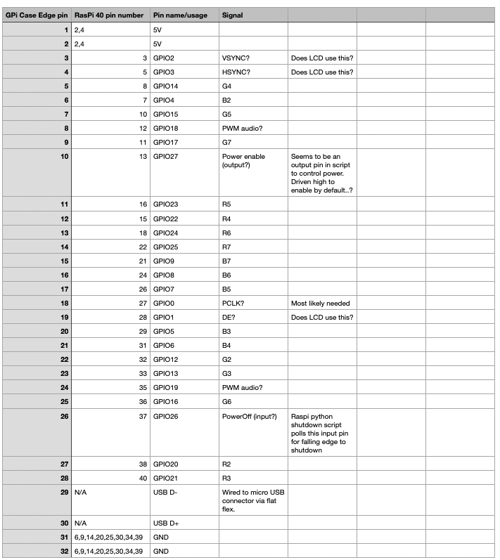
From what I've been able to ascertain, this device seems to use a 32 pin card edge connector with the following signals present (normally from the Raspi GPIO):
18 bits of parallel RGB video (DPI 6:6:6 mode)
CLK, DE, HSYNC, VSYNC signals - which of this set is required by the LCD not sure yet.
2 PWM channels for audio, integrated speaker might be mono and need mixing?
a poweron input signal and a poweroff output if safe shutdown is enabled, but these can be ignored if safe shutdown is disabled (via a slide switch on the main unit)
5V supply input
USB D+/D- for connection to integrated XBOX360 like USB controller reporting button state
The screen is powered via the internal Lipo battery and has an inbuilt amplifier and USB gamepad controller. There is likely a boost converter providing 5V to the Raspi.
This is still a bit of a gamble as I don't know the range of frequencies the LCD supports, and whether or not usbnew will recognise the USB controller hardware (eg. if a USB2.0 or 1.1 HUB etc). Also whether or not any of Ada's emulators can be coaxed to output parallel RGB... Getting a clock signal out is usually okay if pixels are synchronous to the P2 clock, but a DE signal requires setting up a smartpin in PWM mode and doing some extra tweaks to it during vblank to zero it. I've done it with my own video driver SW but not sure about within Ada's code whether that's possible yet. Hopefully it is.
But if all else fails with P2 integration on this device I can always use it with a RasPi Zero and Retropie etc, so all is not lost.
Actually using the P2-Edge may also allow HDMI out as an extra/alternative option.
P0-P23 - parallel RGB
P24-P27 - CLK, DE, H, V
P28-P29 USB D-/D+
P30-P31 PWM audio
P32-P39 HDMI
I can probably also reuse the lower 2 bits of R/G/B as well for additional signals given the LCD edge connector only carries 6 bits per colour channel. That could allow a dedicated SD card to not interfere with on-board boot flash.
@rogloh said:
This is still a bit of a gamble as I don't know the range of frequencies the LCD supports,
If they make a 640x480 LCD that doesn't take VGA-timed signals, that'd be real silly
and whether or not usbnew will recognise the USB controller hardware (eg. if a USB2.0 or 1.1 HUB etc).
Should work OOTB from how you describe it, if not we can prob. fix it
Also whether or not any of Ada's emulators can be coaxed to output parallel RGB...
Yes, easily, though the pin layout should be as-if for 24 bit. Using the unused gap pins for something very non-video is okay. Can maybe put the USB pins there, too.
Getting a clock signal out is usually okay if pixels are synchronous to the P2 clock, but a DE signal requires setting up a smartpin in PWM mode and doing some extra tweaks to it during vblank to zero it. I've done it with my own video driver SW but not sure about within Ada's code whether that's possible yet. Hopefully it is.
??? Why so complicated? DE can just be driven using one of the streamer LSBs, just like HSYNC and VSYNC. Easy.
Thanks Ada for your positive updates above and I expect USB could go in those RBG LSB gaps too. It might also allow more PSRAM chip selects & clocks for a dedicated design with say 64 or 96MB. Yeah I'll go and create a new thread for this actual effort once it arrives and I begin testing and probably do a quick interposer board layout with the Edge connector. I was a little concerned about the emulator side as it's not my own code, and less so the actual HW but we'll see what the deal is once it gets here and I start to try something out. Actually I ordered before 2pm today and got priority shipping from Sydney so it may even arrive tomorrow with any luck, but more likely Monday. I also saw this product available cheap on AliExpress and quite a few other places so that's an option if others also want to try it out. But I don't mind being the guinea pig first since its not 100% guaranteed to work out yet.
@Rayman said:
That case does look interesting …
Might be to professional looking for goals here though….
@rogloh I'll have to show that to my son and see what he thinks...
3" is probably nicer that 2.3", at least for me. But, kids have better vision...
But, he is liking the option for 2 player mode with the extra wireless controller.
Still, maybe one could stick the wireless receiver inside this box too...
@Rayman said:
@rogloh Don't think this needs a new thread really. I'm open to this idea for Logicon.
Ok I'll keep posting here for now. Just checked my order tracking, says it's onboard for delivery today which is good. Now I just have to not miss the delivery.
One thing if you have a 3d printer is you can make custom cartridge housings for this thing so any attached board can get quite big if it needs to be. People have done that for CM3 attachments, although now there is an official CM4 case version too. Ultimately I want to try to fit a small custom P2 PCB inside the existing cartridge if I can and swap between RasPi and P2 cartridges etc, but in the meantime will use a simple edge connector wiring board to plug in the P2-EC32MB for testing.
When it arrives I'll take some measurements and post more details on internal sizing, pinouts etc.
Well it just showed up, less than 24 hours post from Sydney to Melbourne, not bad. I'll post more details about the insides in a bit. Want to reverse engineer the pinout.
Did some probing and measuring with calipers and took more pics. The PCB with the edge connector that connects to the Raspi using pogo pins is 41x63.5mm and 0.8mm thick. The narrower card edge part is 49.5mm wide and 11.3mm long with the edge fingers reaching back 7.5mm from the edge. Pin pitch seems to be 1.5mm.
The height available from the surface of this board to the (deepest) plastic case parts underneath is 6mm and about 5mm where blocked by the pattern of stiffening regions.
A P2 edge connector can fit onto the board. Height means it will protrude through the cartridge plastic which needs to be cut and is to be expected.
A dedicated P2 board could potentially fit inside as shown by a P2-Edge's size relative to this case.
I also buzzed out the connector (aligning pin1 with the leftmost edge of the board printed with a + symbol on the silkscreen). Here's the mapping I found:
It's probably even possible to run without the cartridge backshell fitted and just feed a P2-Edge directly to the connector without hacking any plastic. Once properly seated flat the P2-edge connector height would line up just under the height of the GPi 2W case and looks quite neat in it's own right.
Update: For initial testing I think I might make a board that has the 40 way Raspi header and the P2 Edge connector and uses the pogo pins to contact my board. I will have to wire in a separate micro usb socket to this board as well, but it's a simpler test board than getting the edge fingers fully right first go.
I did just check without anything connected and the main power switch turned on that 5V was present between pins 1,2 and 31,32. So the Lipo boost converter is definitely active. Nothing was visible on the LCD screen, so I'm guessing the micro on the main board detects signals before powering it up and turning on the backlight etc. I was also reading somewhere that you can run it as an XBOX 360 style USB controller via its own dedicated micro USB port accessible under the battery cover that is also used for firmware upgrades. Will have to try that out at some point.
Here's the rough idea of what I am intending to do for testing (from KiCad). Forget the 2x20 pin header in the 3d render, that's just where the pogo pins would connect. Just need to figure out the P2 pin assignments for the layout.
@Wuerfel_21 do you have any input here as to what best to do for DE/VSYNC/HSYNC/PCLK signals and your drivers so it has the best chance of working first go? I'm only intending to use the P2-Edge EC32MB signals from P0-P39. Should we associate pins 0-23 for RGB or pins 8-31 for RGB leaving some lower accessible ones in the P0-7 range for DE & SYNCs etc? I guess I can just put USB and audio somewhere and the power on/off signals up on P32-P39 to make room. No need for any spare HDMI output pins for now during testing. Not sure where the PCLK should be located, probably also in the P32-P39 range to keep it from messing up the streamed video. Can't recall if streaming video overrides smartpins controlled from the same COG, I know it's one or the other and there were restrictions there. Also were there any issues with P2EC32MB and any fast transitioning signals on P28-P31 with PLL jitter or was that board revision fixed??? I wonder if the red video signals would mess anything up there.
EDIT: wiring looks a bit nasty assuming P8-P31 for RGB use (in fact it's P10-P15, P18-P23, P26-P31 for BGR). Might have to go 4 layers.
Turns out 2 layers can route all the signals, but the ground connections got trashed and isolated so I'll just have to go to 4 layers (although we probably don't need to connect to all of them). It will help signal integrity anyway too.
Ostensibly 8-31 is better, but I think the signals wrap around within the port (TODO confirm?), so you can do 0-23, too.
Assuming 8-31 for BGR, the HSYNC/VSYNC/DE should go either on 0-2 or 5-7. Clock should probably also be around there, but doesn't really matter since that's its own smartpin. Putting other stuff on the 8 pins that correspond to streamer channel 0 shouldn't be an issue, since they never go high unless asked to. The other stuff I'll need to check.
P2EDGE uses an active oscillator, so shouldn't have the PLL issue. The signal will only switch at ~13 MHz anyways, not so high-speed at all.
Audio probably should go on the other port, just to be away from all the 60Hz waveforms.
@Wuerfel_21 said:
Ostensibly 8-31 is better, but I think the signals wrap around within the port (TODO confirm?), so you can do 0-23, too.
Assuming 8-31 for BGR, the HSYNC/VSYNC/DE should go either on 0-2 or 5-7. Clock should probably also be around there, but doesn't really matter since that's its own smartpin. Putting other stuff on the 8 pins that correspond to streamer channel 0 shouldn't be an issue, since they never go high unless asked to. The other stuff I'll need to check.
P2EDGE uses an active oscillator, so shouldn't have the PLL issue. The signal will only switch at ~13 MHz anyways, not so high-speed at all.
Audio probably should go on the other port, just to be away from all the 60Hz waveforms.
Ok, thanks. For now I've placed V/H/DE on 5-7 and kept the BGR video on 8-31 (with 2 LSB gaps per colour). All the other non-video stuff is already up at P32-P39 along with the pixel clock which I think can be located up there too (as it's closer to run to the final RasPi header pin and away from interfering with most of the other signals). I added the other inner layers as ground planes and routed in the extra ground pins that were isolated before, so it's essentially done now electrically. If you can, let me know asap if you do think of any issues otherwise this schematic might be the final mapping. Just need to tidy up final board cut dimensions and drill hole mounting positions now before ready to send it off.
Video stuff LGTM.
Not sure what's going on with the USB? Shouldn't that also go to the connector? (and host-side should really not be on a micro-B) Also not entirely sure how the driver copes with not having power management (i.e. if you reset the P2 does the driver manage to pick off from the already-initialized state?)
Also, just remembered another software limitation in my code, pin 0 (DIGITAL_BASEPIN in this scenario) gets blasted with WXPINs due to the HDMI audio implementation. Currently not hooked to anything, but maybe smarter to move H/V/DE down? That's just a software meme though, can be fixed if push comes to shove.
@Wuerfel_21 said:
Video stuff LGTM.
Not sure what's going on with the USB? Shouldn't that also go to the connector? (and host-side should really not be on a micro-B) Also not entirely sure how the driver copes with not having power management (i.e. if you reset the P2 does the driver manage to pick off from the already-initialized state?)
From what I imagine is that the USB port would be acting as host via OTG on the RasPi Zero's micro-AB port and the RPi would poll the USB controller. I don't think they have special software on the Pi acting as a device client that gets pushed the button state, instead the Pi just polls the USB device. Now as far as the attachment stage goes, it's sort of always connected from bootup internally so hopefully the state machine in usbnew can cope with that and doesn't need to wait for an explicit connection. But perhaps the micro on board the RPi Case 2W does something fancy and triggers a bus attachment somehow - this is a bit of an unknown however. For now I want to assume it's going to be able to work one way or another and won't be a show stopper.... famous last words I guess.
Also, just remembered another software limitation in my code, pin 0 (DIGITAL_BASEPIN in this scenario) gets blasted with WXPINs due to the HDMI audio implementation. Currently not hooked to anything, but maybe smarter to move H/V/DE down? That's just a software meme though, can be fixed if push comes to shove.
What is the actual reason for considering moving H/V/DE down from 5,6,7 ? Where is the DIGITAL_BASEPIN again in your code - it's on the HDMI base pin right? If it can be nominated as anything I do have a spare pin separate to the streamer stuff up at P39 if that helps? Other free pins are at 0,1,2,3,4,8,9,16,17,24,25.
@rogloh said:
For now I want to assume it's going to be able to work one way or another and won't be a show stopper.... famous last words I guess.
It should at the very least work on a cold boot. I think someone somewhere had a board without USB power control, I remember specifically adding the option to not have that pin. But IDK if that worked well or caused problems.
Also, just remembered another software limitation in my code, pin 0 (DIGITAL_BASEPIN in this scenario) gets blasted with WXPINs due to the HDMI audio implementation. Currently not hooked to anything, but maybe smarter to move H/V/DE down? That's just a software meme though, can be fixed if push comes to shove.
What is the actual reason for considering moving H/V/DE down from 5,6,7 ? Where is the DIGITAL_BASEPIN again in your code - it's on the HDMI base pin right? If it can be nominated as anything I do have a spare pin separate to the streamer stuff up at P39 if that helps? Other free pins are at 0,1,2,3,4,8,9,16,17,24,25.
If there's no digital audio out, there's no pin needed, it's just easier to make the sound cog always write to a digital basepin if it exists in the config at all (not -1). So if the basepin isn't actually used by the LCD format, whatever else ends up there gets blasted with audio samples just because it's harder to not do that. So it's better to use the base pin for something harmless like HSYNC (which would never be in a smart mode that cares about the X register). But again, that doesn't break for your current proto that doesn't have P0 on anything at all
@rogloh said:
For now I want to assume it's going to be able to work one way or another and won't be a show stopper.... famous last words I guess.
It should at the very least work on a cold boot. I think someone somewhere had a board without USB power control, I remember specifically adding the option to not have that pin. But IDK if that worked well or caused problems.
I know I have used your usbnew at some point without USB power control and it worked at that time. Hopefully the USB interface in this thing is reasonably dumb and may just expose D+/D- to the pins without needing a lot of fancy negotiation first. I do have a spare pin that could be wired in to a 1.5k pullup attached to one of the D pins (via solder jumper) which could then be detached dynamically perhaps to emulate switching from device mode into an OTG style host mode - or we could even use the internal 1.5k GPIO drive option of the P2 pin to avoid the resistor completely. That way a solder jumper could be connecting the D- and another IO pin at P39 for acting as a low speed device. If it didn't work out we just don't solder the jumper (or leave it shorted but floating). That's a zero cost harmless thing to add so I'll probably add it in case it might help. I'll make it allow D+ use as well.
If there's no digital audio out, there's no pin needed, it's just easier to make the sound cog always write to a digital basepin if it exists in the config at all (not -1). So if the basepin isn't actually used by the LCD format, whatever else ends up there gets blasted with audio samples just because it's harder to not do that. So it's better to use the base pin for something harmless like HSYNC (which would never be in a smart mode that cares about the X register). But again, that doesn't break for your current proto that doesn't have P0 on anything at all
Yeah I'll leave things as is. Probably needs further consideration in any final custom P2 board that may also have HDMI and digital out desired. That would have different IO mapping anyway.
I'm very close now. I'll post the KiCad files and Mouser BOM as well soon if others also want to make one up at some point. One other thing is I'll probably bring the PropPlug out the uSD card opening for easy attachment. The 4 pin PropPlug header should fit nicely through that existing cut out in the cartridge. Just need to make an SMD footprint and find a right angle pin header and adjust the layout slightly.
I've made this adapter board which I'm now codenaming the little FireAnt the same size as a RasPi Zero and from a mounting point of view I think the Pogo pins are going to need pressure applied to work right so the cartridge's plastic backshell really still needs to be affixed. I think I can keep three of the four internal tiny (~1mm ID threaded and 2.5mm OD) metal mounting bosses that get screwed into, but the fourth one may need to be hacked out with some blade work to make room for the larger P2-Edge connector to pass by - it's just a tad too wide to fit without removal unfortunately. However it should still be sturdy enough after that I would expect and if not that little metal boss could be moved slightly and glued in a different place if required. The P2-Edge PCB will then slide in behind the cartridge through the partially exposed edge connector at the back.
BOM UPDATE: (Qty, Mouser part #, Description)
1,640-USB3076-30-A, USB Micro-B connector
1,619-450-00308, Parallax 80 pin Edge connector R/A
1, 855-M20-8900405, 4 pin 0.1 inch SMD header R/A
Ok we are done. This should be final now I expect and dimensions should be good. Gerbers attached in zip file for anyone else keen to try this as well as me (4 layer PCB). The BOM was already shown above (only 3 items are needed for this simple board). A solder jumper has been added to optionally connect P2 IO pin 39 to either USB D+ or D- signals for a simulated pullup resistor to (re)trigger USB device attachment at startup etc (or we can leave it unsoldered if having this ends up being useless or harmful). It is a spare pin otherwise.
EDIT: I just added in pad vias on the Prop Plug pads to try to stiffen them against ripping out with the SMD header pins flexing. This is in the separate zipfile called gpi2w-vias.zip (in case your fab house can't put vias in pads you can use the original).
EDIT2: hold the phone, the Raspi connector position got shifted and PCB needs a fixup tweak. Will repost fixed gerbers when this is done. EDIT3: Ok fixed now. Gerbers should be good again.
@Tubular said:
Just catching up, crikey you have been busy. Nice find on the case.
Busy yeah, and it's good practice learning KiCad right now. I've emailed you some of these files too if boards are going out soon. The case I found should be great if it all works out, still a small gamble on the USB controller side, though I expect the LCD + audio stuff will probably be usable. We'll see soon enough once this FireAnt PCB comes back.
It'd be good to try to test something in the meantime but the rear cover occludes the pogo pins for direct probing and some type of adapter board really needs to bring the signals out beyond that. If I can solder some wires onto some 0.1 inch matrix board to 6x2 headers I might be able to hook in a P2-EVAL for testing the video timing or USB controller perhaps in the meantime. The problem is any attached board needs pressure applied to make a proper contact to the pogo pins and will slip off easily without clamping it down. Although maybe I can solder something onto the gold edge fingers directly for USB signal tests. Trying not to trash the edge connector however. If I attach the microUSB flex to the Parallax Serial device breakout accessory and wire in a common ground wire to the gold square ground pad (this USB connector floats) it might be possible to test the USB but only if it works without the screen being active first....
Ah, I see, that's what's going on with the USB connector. They designed it to plug into the Pi Zero. Yeah that's just doing OTG, which should work passively if you're just trying to be a host. I think an actual OTG device needs that extra 5th pin to do something to switch into host mode, but we just assume we're a host (and I think the Pi Zero does, too? I don't think it can do device mode?) So trying it with the Serial Device accessory is fine if you can manage that.
You're saying this USB connector doesn't have GND and VBUS connected to anything? That'd be odd.


Comments
That doesn't work, the putstring function takes different arguments (and for the way MegaYume UI is, you'd really want to use msgbox_simple).
Though the whole error case is low-key nonsense, I think it almost never fails with a mount error, even if there's no media inserted.
(Unrelatedly, I wish there was a better way to work with flash files. I tried generating PFS images offline but it never really worked. Though to make it really useful I think I need to add an ability to compress ROM files)
Fun project @Rayman. What sort of 2.3 inch screen is that exactly ? I've been meaning to hunt down something that works with MegaYume etc to replace a screen and create a similar handheld P2 powered console, with this device below as the basis. Unfortunately I can't easily seem to figure out its existing actual screen interface with probing so it's probably simpler to replace it, but many are the wrong aspect ratio, I need true landscape vs portrait mode LCD I think.
It’s the 2.3” modules from buydisplay.com
They have a special driver that allows landscape scan in rgb mode. So it’s basically a digital version of vga.
Seems the other displays are either portrait or don’t have rgb mode.
Wish it were bigger but this seems fine with intended audience.
That one's called ILI9342. My driver uses the 6 bit RGB + HV mode.
Though it can really be adapted to anything quite easily, as long as it doesn't require transposing the data (because it only comes in line-by-line) or too much CPU-side format conversion. I think I said doing a 640x480 LCD with the 16 bit scheme that @Rayman came up with is doable, if he sent me a proto of that I'd probably get it working.
So @Wuerfel_21 is that 6 bits per pixel or 18 bits per pixel (6 bits per colour?), hopefully the latter or it's just 64 total colours which would surely suck.
18 bits, but sent sequentially over 6 wires. I think we had that question before. Read datasheet, etc etc.
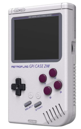
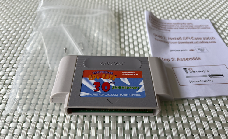
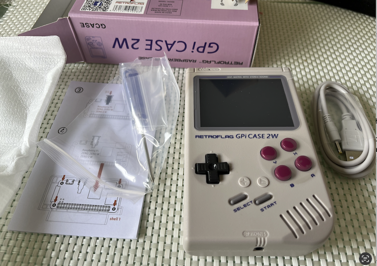
I think this handheld case could be promising for a P2 handheld console device hack (at least vs what I posted above). On a custom P2 PCB using the standard Raspi Zero form factor we could feed parallel RGB video, PWM audio and USB for the button controller out the same GPIO pin positions the Raspi Zero 2W uses and to a single micro-usb connector attached to the existing flat flex cable provided. Pogo pin connections to the enclosing cartridge's IO conversion board adapting to an edge connector into the main screen board make it simple to swap over from a Raspi and you'd still have external access to a microSD for files. There is another more advanced version of this case that even offers a dock with HDMI which could also work as a basis for a console but the CM4 interface is more complex to design for. This 2W case version uses a larger 3 inch landscape 640x480 IPS screen which potentially works nicer with Ada's emulators and other applications that need higher resolution than 320x240. I might get one to try out.
https://core-electronics.com.au/retroflag-gpi-2w-handheld-console.html
EDIT: actually once you know the edge connector pinout used by the cartridge you could probably simplify things and bypass the whole pogo pin route and redo the adapter board inside the cartridge to hold the P2 itself, plus that gives you a bit more space to lay it out. Just wire in Parallel RGB, PWM audio, USB, power and the microSD card for a filesystem. You'd still have enough leftover pins on a P2 to add quite a bit of 16 bit wide PSRAM too (64MB or maybe 96MB).
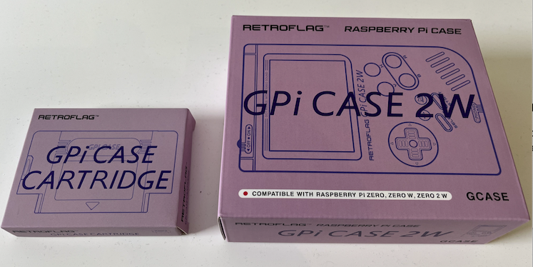
So I just bit the bullet and ordered one of these GPi Case 2W handhelds plus an additional empty cartridge that I can mod with a P2. Initially might even just make up an adapter board with the P2-Edge connector and simply slide in a P2-Edge EC32MB externally for the fastest solution.
From what I've been able to ascertain, this device seems to use a 32 pin card edge connector with the following signals present (normally from the Raspi GPIO):
The screen is powered via the internal Lipo battery and has an inbuilt amplifier and USB gamepad controller. There is likely a boost converter providing 5V to the Raspi.
This is still a bit of a gamble as I don't know the range of frequencies the LCD supports, and whether or not usbnew will recognise the USB controller hardware (eg. if a USB2.0 or 1.1 HUB etc). Also whether or not any of Ada's emulators can be coaxed to output parallel RGB... Getting a clock signal out is usually okay if pixels are synchronous to the P2 clock, but a DE signal requires setting up a smartpin in PWM mode and doing some extra tweaks to it during vblank to zero it. I've done it with my own video driver SW but not sure about within Ada's code whether that's possible yet. Hopefully it is.
But if all else fails with P2 integration on this device I can always use it with a RasPi Zero and Retropie etc, so all is not lost.
Actually using the P2-Edge may also allow HDMI out as an extra/alternative option.
P0-P23 - parallel RGB
P24-P27 - CLK, DE, H, V
P28-P29 USB D-/D+
P30-P31 PWM audio
P32-P39 HDMI
I can probably also reuse the lower 2 bits of R/G/B as well for additional signals given the LCD edge connector only carries 6 bits per colour channel. That could allow a dedicated SD card to not interfere with on-board boot flash.
If they make a 640x480 LCD that doesn't take VGA-timed signals, that'd be real silly
Should work OOTB from how you describe it, if not we can prob. fix it
Yes, easily, though the pin layout should be as-if for 24 bit. Using the unused gap pins for something very non-video is okay. Can maybe put the USB pins there, too.
??? Why so complicated? DE can just be driven using one of the streamer LSBs, just like HSYNC and VSYNC. Easy.
That case does look interesting …
Might be to professional looking for goals here though….
What is display size?
Different project, maybe you should ask for a thread split?
Thanks Ada for your positive updates above and I expect USB could go in those RBG LSB gaps too. It might also allow more PSRAM chip selects & clocks for a dedicated design with say 64 or 96MB. Yeah I'll go and create a new thread for this actual effort once it arrives and I begin testing and probably do a quick interposer board layout with the Edge connector. I was a little concerned about the emulator side as it's not my own code, and less so the actual HW but we'll see what the deal is once it gets here and I start to try something out. Actually I ordered before 2pm today and got priority shipping from Sydney so it may even arrive tomorrow with any luck, but more likely Monday. I also saw this product available cheap on AliExpress and quite a few other places so that's an option if others also want to try it out. But I don't mind being the guinea pig first since its not 100% guaranteed to work out yet.
3 inch 640x480 LCD.

Here's a nice review.
@rogloh I'll have to show that to my son and see what he thinks...
3" is probably nicer that 2.3", at least for me. But, kids have better vision...
But, he is liking the option for 2 player mode with the extra wireless controller.
Still, maybe one could stick the wireless receiver inside this box too...
@rogloh Don't think this needs a new thread really. I'm open to this idea for Logicon.
End user says we could call that one Logicon Pocket
Although it might be too big for that exactly. Have to look up dimensions.
Ok I'll keep posting here for now. Just checked my order tracking, says it's onboard for delivery today which is good. Now I just have to not miss the delivery.
One thing if you have a 3d printer is you can make custom cartridge housings for this thing so any attached board can get quite big if it needs to be. People have done that for CM3 attachments, although now there is an official CM4 case version too. Ultimately I want to try to fit a small custom P2 PCB inside the existing cartridge if I can and swap between RasPi and P2 cartridges etc, but in the meantime will use a simple edge connector wiring board to plug in the P2-EC32MB for testing.
When it arrives I'll take some measurements and post more details on internal sizing, pinouts etc.
Well it just showed up, less than 24 hours post from Sydney to Melbourne, not bad. I'll post more details about the insides in a bit. Want to reverse engineer the pinout.
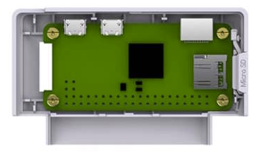
Did some probing and measuring with calipers and took more pics. The PCB with the edge connector that connects to the Raspi using pogo pins is 41x63.5mm and 0.8mm thick. The narrower card edge part is 49.5mm wide and 11.3mm long with the edge fingers reaching back 7.5mm from the edge. Pin pitch seems to be 1.5mm.
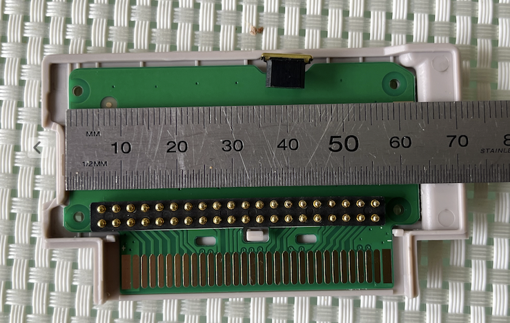
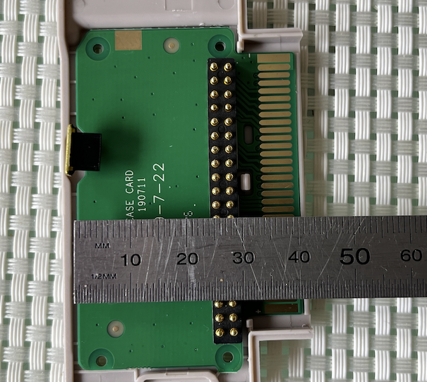
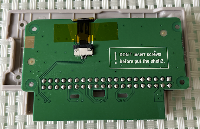
The height available from the surface of this board to the (deepest) plastic case parts underneath is 6mm and about 5mm where blocked by the pattern of stiffening regions.
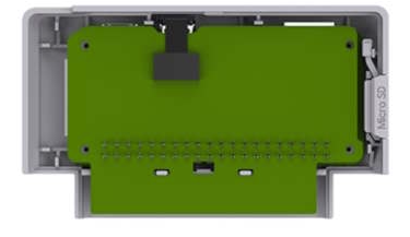
A P2 edge connector can fit onto the board. Height means it will protrude through the cartridge plastic which needs to be cut and is to be expected.
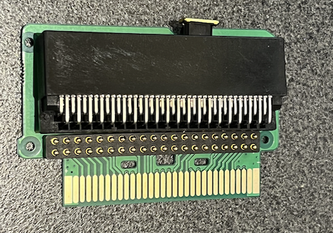
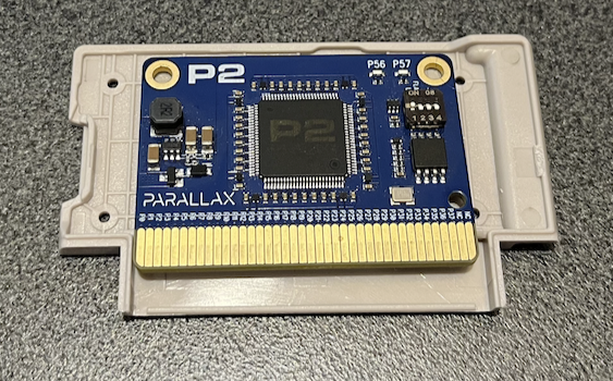
A dedicated P2 board could potentially fit inside as shown by a P2-Edge's size relative to this case.
I also buzzed out the connector (aligning pin1 with the leftmost edge of the board printed with a + symbol on the silkscreen). Here's the mapping I found:
It's probably even possible to run without the cartridge backshell fitted and just feed a P2-Edge directly to the connector without hacking any plastic. Once properly seated flat the P2-edge connector height would line up just under the height of the GPi 2W case and looks quite neat in it's own right.
Update: For initial testing I think I might make a board that has the 40 way Raspi header and the P2 Edge connector and uses the pogo pins to contact my board. I will have to wire in a separate micro usb socket to this board as well, but it's a simpler test board than getting the edge fingers fully right first go.
I did just check without anything connected and the main power switch turned on that 5V was present between pins 1,2 and 31,32. So the Lipo boost converter is definitely active. Nothing was visible on the LCD screen, so I'm guessing the micro on the main board detects signals before powering it up and turning on the backlight etc. I was also reading somewhere that you can run it as an XBOX 360 style USB controller via its own dedicated micro USB port accessible under the battery cover that is also used for firmware upgrades. Will have to try that out at some point.
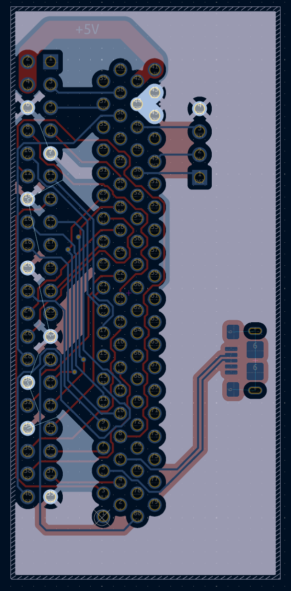
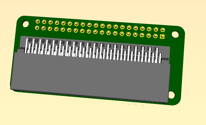
Here's the rough idea of what I am intending to do for testing (from KiCad). Forget the 2x20 pin header in the 3d render, that's just where the pogo pins would connect. Just need to figure out the P2 pin assignments for the layout.
@Wuerfel_21 do you have any input here as to what best to do for DE/VSYNC/HSYNC/PCLK signals and your drivers so it has the best chance of working first go? I'm only intending to use the P2-Edge EC32MB signals from P0-P39. Should we associate pins 0-23 for RGB or pins 8-31 for RGB leaving some lower accessible ones in the P0-7 range for DE & SYNCs etc? I guess I can just put USB and audio somewhere and the power on/off signals up on P32-P39 to make room. No need for any spare HDMI output pins for now during testing. Not sure where the PCLK should be located, probably also in the P32-P39 range to keep it from messing up the streamed video. Can't recall if streaming video overrides smartpins controlled from the same COG, I know it's one or the other and there were restrictions there. Also were there any issues with P2EC32MB and any fast transitioning signals on P28-P31 with PLL jitter or was that board revision fixed??? I wonder if the red video signals would mess anything up there.
EDIT: wiring looks a bit nasty assuming P8-P31 for RGB use (in fact it's P10-P15, P18-P23, P26-P31 for BGR). Might have to go 4 layers.
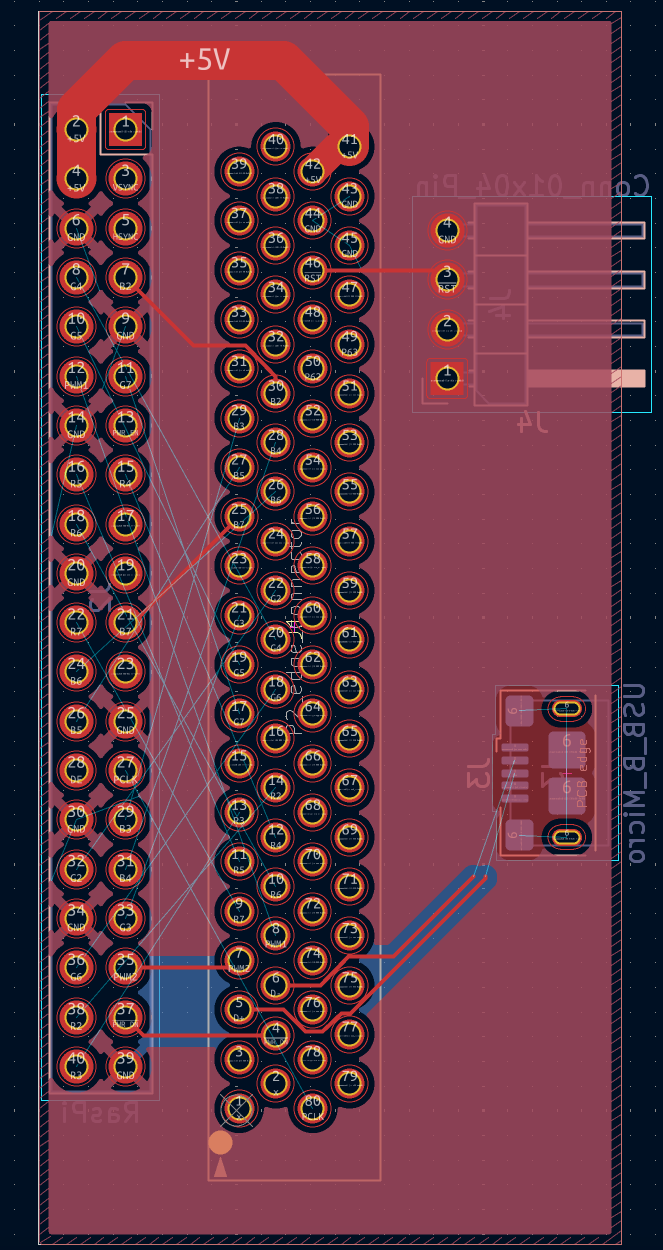
Turns out 2 layers can route all the signals, but the ground connections got trashed and isolated so I'll just have to go to 4 layers (although we probably don't need to connect to all of them). It will help signal integrity anyway too.
Ostensibly 8-31 is better, but I think the signals wrap around within the port (TODO confirm?), so you can do 0-23, too.
Assuming 8-31 for BGR, the HSYNC/VSYNC/DE should go either on 0-2 or 5-7. Clock should probably also be around there, but doesn't really matter since that's its own smartpin. Putting other stuff on the 8 pins that correspond to streamer channel 0 shouldn't be an issue, since they never go high unless asked to. The other stuff I'll need to check.
P2EDGE uses an active oscillator, so shouldn't have the PLL issue. The signal will only switch at ~13 MHz anyways, not so high-speed at all.
Audio probably should go on the other port, just to be away from all the 60Hz waveforms.
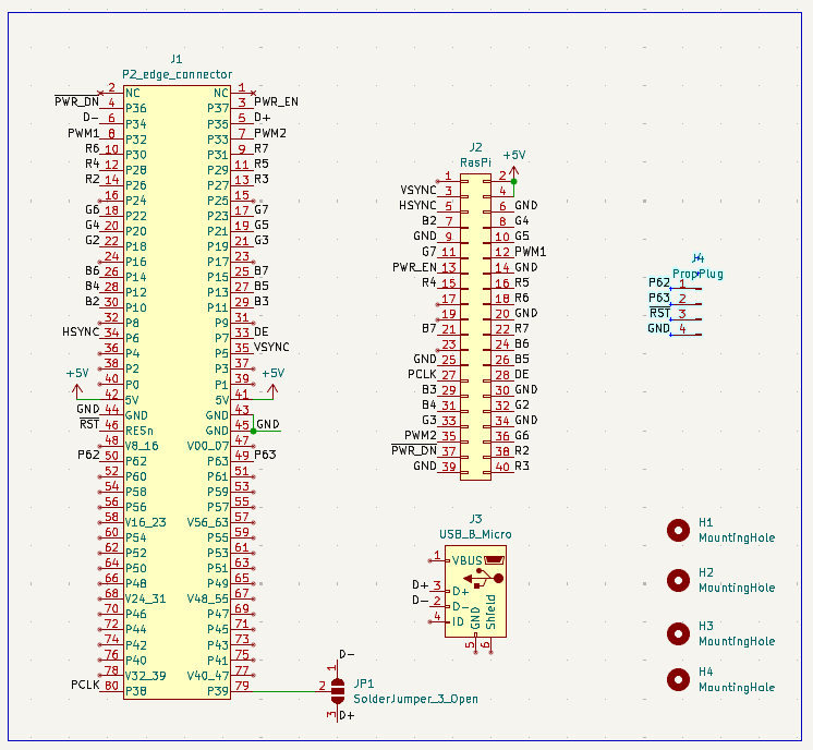
Ok, thanks. For now I've placed V/H/DE on 5-7 and kept the BGR video on 8-31 (with 2 LSB gaps per colour). All the other non-video stuff is already up at P32-P39 along with the pixel clock which I think can be located up there too (as it's closer to run to the final RasPi header pin and away from interfering with most of the other signals). I added the other inner layers as ground planes and routed in the extra ground pins that were isolated before, so it's essentially done now electrically. If you can, let me know asap if you do think of any issues otherwise this schematic might be the final mapping. Just need to tidy up final board cut dimensions and drill hole mounting positions now before ready to send it off.
Video stuff LGTM.
Not sure what's going on with the USB? Shouldn't that also go to the connector? (and host-side should really not be on a micro-B) Also not entirely sure how the driver copes with not having power management (i.e. if you reset the P2 does the driver manage to pick off from the already-initialized state?)
Also, just remembered another software limitation in my code, pin 0 (DIGITAL_BASEPIN in this scenario) gets blasted with WXPINs due to the HDMI audio implementation. Currently not hooked to anything, but maybe smarter to move H/V/DE down? That's just a software meme though, can be fixed if push comes to shove.
From what I imagine is that the USB port would be acting as host via OTG on the RasPi Zero's micro-AB port and the RPi would poll the USB controller. I don't think they have special software on the Pi acting as a device client that gets pushed the button state, instead the Pi just polls the USB device. Now as far as the attachment stage goes, it's sort of always connected from bootup internally so hopefully the state machine in usbnew can cope with that and doesn't need to wait for an explicit connection. But perhaps the micro on board the RPi Case 2W does something fancy and triggers a bus attachment somehow - this is a bit of an unknown however. For now I want to assume it's going to be able to work one way or another and won't be a show stopper.... famous last words I guess.
What is the actual reason for considering moving H/V/DE down from 5,6,7 ? Where is the DIGITAL_BASEPIN again in your code - it's on the HDMI base pin right? If it can be nominated as anything I do have a spare pin separate to the streamer stuff up at P39 if that helps? Other free pins are at 0,1,2,3,4,8,9,16,17,24,25.
It should at the very least work on a cold boot. I think someone somewhere had a board without USB power control, I remember specifically adding the option to not have that pin. But IDK if that worked well or caused problems.
If there's no digital audio out, there's no pin needed, it's just easier to make the sound cog always write to a digital basepin if it exists in the config at all (not -1). So if the basepin isn't actually used by the LCD format, whatever else ends up there gets blasted with audio samples just because it's harder to not do that. So it's better to use the base pin for something harmless like HSYNC (which would never be in a smart mode that cares about the X register). But again, that doesn't break for your current proto that doesn't have P0 on anything at all
I know I have used your usbnew at some point without USB power control and it worked at that time. Hopefully the USB interface in this thing is reasonably dumb and may just expose D+/D- to the pins without needing a lot of fancy negotiation first. I do have a spare pin that could be wired in to a 1.5k pullup attached to one of the D pins (via solder jumper) which could then be detached dynamically perhaps to emulate switching from device mode into an OTG style host mode - or we could even use the internal 1.5k GPIO drive option of the P2 pin to avoid the resistor completely. That way a solder jumper could be connecting the D- and another IO pin at P39 for acting as a low speed device. If it didn't work out we just don't solder the jumper (or leave it shorted but floating). That's a zero cost harmless thing to add so I'll probably add it in case it might help. I'll make it allow D+ use as well.
Yeah I'll leave things as is. Probably needs further consideration in any final custom P2 board that may also have HDMI and digital out desired. That would have different IO mapping anyway.
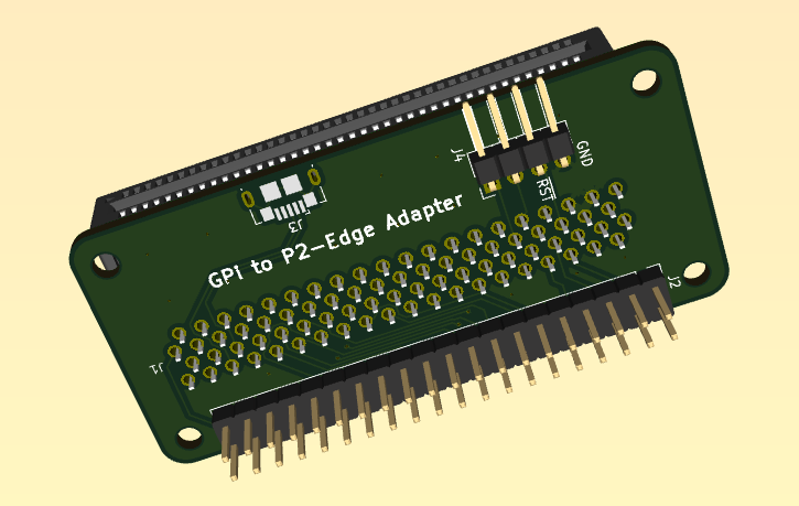
I'm very close now. I'll post the KiCad files and Mouser BOM as well soon if others also want to make one up at some point. One other thing is I'll probably bring the PropPlug out the uSD card opening for easy attachment. The 4 pin PropPlug header should fit nicely through that existing cut out in the cartridge. Just need to make an SMD footprint and find a right angle pin header and adjust the layout slightly.
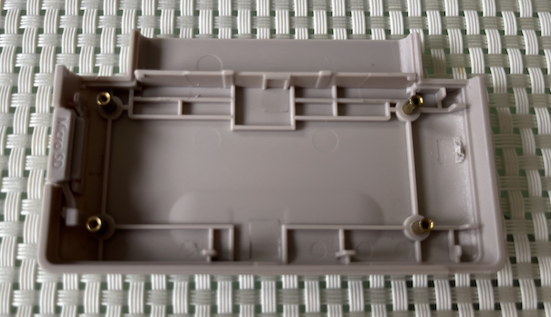
I've made this adapter board which I'm now codenaming the little FireAnt the same size as a RasPi Zero and from a mounting point of view I think the Pogo pins are going to need pressure applied to work right so the cartridge's plastic backshell really still needs to be affixed. I think I can keep three of the four internal tiny (~1mm ID threaded and 2.5mm OD) metal mounting bosses that get screwed into, but the fourth one may need to be hacked out with some blade work to make room for the larger P2-Edge connector to pass by - it's just a tad too wide to fit without removal unfortunately. However it should still be sturdy enough after that I would expect and if not that little metal boss could be moved slightly and glued in a different place if required. The P2-Edge PCB will then slide in behind the cartridge through the partially exposed edge connector at the back.
BOM UPDATE: (Qty, Mouser part #, Description)
1,640-USB3076-30-A, USB Micro-B connector
1,619-450-00308, Parallax 80 pin Edge connector R/A
1, 855-M20-8900405, 4 pin 0.1 inch SMD header R/A
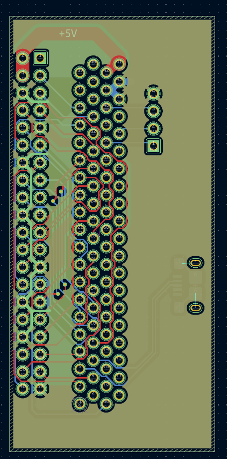
Ok we are done. This should be final now I expect and dimensions should be good. Gerbers attached in zip file for anyone else keen to try this as well as me (4 layer PCB). The BOM was already shown above (only 3 items are needed for this simple board). A solder jumper has been added to optionally connect P2 IO pin 39 to either USB D+ or D- signals for a simulated pullup resistor to (re)trigger USB device attachment at startup etc (or we can leave it unsoldered if having this ends up being useless or harmful). It is a spare pin otherwise.
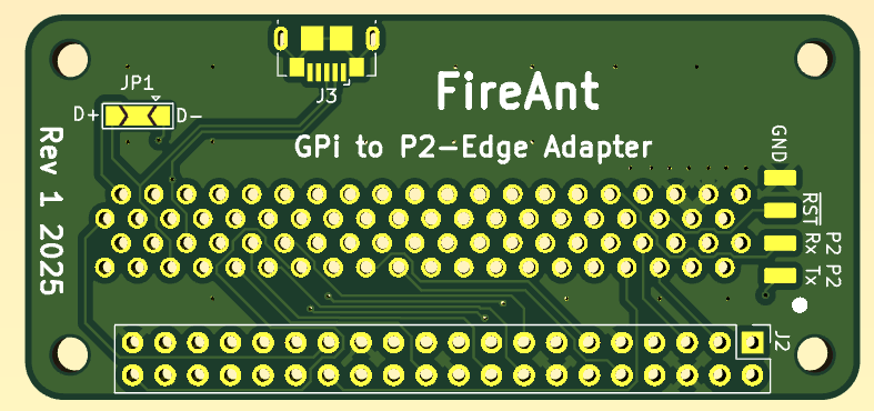
EDIT: I just added in pad vias on the Prop Plug pads to try to stiffen them against ripping out with the SMD header pins flexing. This is in the separate zipfile called gpi2w-vias.zip (in case your fab house can't put vias in pads you can use the original).
EDIT2: hold the phone, the Raspi connector position got shifted and PCB needs a fixup tweak. Will repost fixed gerbers when this is done. EDIT3: Ok fixed now. Gerbers should be good again.
Just catching up, crikey you have been busy. Nice find on the case.
Busy yeah, and it's good practice learning KiCad right now. I've emailed you some of these files too if boards are going out soon. The case I found should be great if it all works out, still a small gamble on the USB controller side, though I expect the LCD + audio stuff will probably be usable. We'll see soon enough once this FireAnt PCB comes back.
It'd be good to try to test something in the meantime but the rear cover occludes the pogo pins for direct probing and some type of adapter board really needs to bring the signals out beyond that. If I can solder some wires onto some 0.1 inch matrix board to 6x2 headers I might be able to hook in a P2-EVAL for testing the video timing or USB controller perhaps in the meantime. The problem is any attached board needs pressure applied to make a proper contact to the pogo pins and will slip off easily without clamping it down. Although maybe I can solder something onto the gold edge fingers directly for USB signal tests. Trying not to trash the edge connector however. If I attach the microUSB flex to the Parallax Serial device breakout accessory and wire in a common ground wire to the gold square ground pad (this USB connector floats) it might be possible to test the USB but only if it works without the screen being active first....
Ah, I see, that's what's going on with the USB connector. They designed it to plug into the Pi Zero. Yeah that's just doing OTG, which should work passively if you're just trying to be a host. I think an actual OTG device needs that extra 5th pin to do something to switch into host mode, but we just assume we're a host (and I think the Pi Zero does, too? I don't think it can do device mode?) So trying it with the Serial Device accessory is fine if you can manage that.
You're saying this USB connector doesn't have GND and VBUS connected to anything? That'd be odd.