

Towards an industrial P2 / PC solution
 Tubular
Posts: 4,771
Tubular
Posts: 4,771
I've been working on a factory floor R&D project that currently involves both a P2 and PC. In the medium/long term, it would be good for the P2 to take over most functions from the PC, especially the time-critical ones
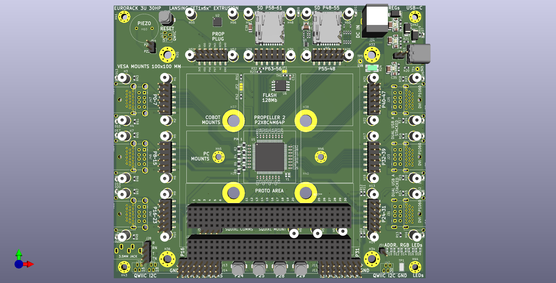
The attached design is what I've come up with. It sits somewhere in between P2-eval, the P1 demo board, and the P1 PPDB. The 88x88mm area in the middle can be for the PC we currently use, a Blackview MP80, or my friend unexpectedmaker's "Squixl" ESP32 based touch display, or a Proto area.
The Blackview has three HDMI sockets on left, and three USB 3 type A sockets on right side. It has two RJ45 lan sockets and power in at the top. I wanted to preserve roughly the same cable setup, but realised I can triple-footprint each 8 bit port to have
- a P2 accessory header, with solder nuts for securing boards or 1"x1" sparkfun sensors
- a dual stacked USB A, with 2 leds, compatible with the serial host accessory board
- a through hole HDMI/DVI connector we can buy locally (seem rare elsewhere)
There's other stuff on the board, most can be jumpered/patched in as required.
As for mounting there are at least 4 options
- Vesa 100x100 to mount on back of monitors
- Cobot mount (M6 bolts, 50mm PCD) - eg Universal Robots
- Eurorack ~ 3U 30HP
- Lansing 'ET' type AL extrusion, 6" long, connectors at ends
The Blackview connectors are all elevated quite high in its case, allowing the P2 boards to happily sit under any PC connections.
Once this board is settled I'm going to compact version, working codename is "brady bunch" because it'll have the P2 in the middle and the 8 sockets packed all around. In this scenario the P2 boards and connections effectively fit on top of the upside-down PC, for a compact 88x88mm overall footprint. You can see the squares in the render.
Comments
I forgot to mention a couple of other features
Is a PC even required anymore?
Yeah unfortunately, things that are easier on the PC include adding a webcam(s) to inspect/record whats happening on a production line, or running some special tuning/config software that came with a high end drive or sensor, or connecting to some propriety gadget that only has windows drivers. Plus these things are only about ~$200 and include a windows license that can happily run stand-alone sans microsoft accounts etc
The other thing it helps with is letting on-site personnel copy off large amounts of data and just sending you the physical drive - its something they're likely be familiar enough with.
Eventually though the PC becomes a liability - they fail, they need updating, can't necessarily get something in the same form factor, etc.
Here's the earlier setup with the PC attached on the back of a touch screen monitor. The blue lasercut acrylic has holes where I was originally thinking of installing P2 accessory headers, before realising 3-a-side was more useful than copying P2eval
The Blackview MP80 is almost exactly the same size as P2-eval.
This will be a nice board design to have around @Tubular . Glad you switched to switching regs for higher voltage operation. I can already see myself wanting to make a handy PSRAM expansion board for the triple wide Parallax expansion header layout down one side, with multiple chip selects on the first 8 IO pins and the 16 bit data on the upper 16 pins. Or you could use the Parallax HyperRAM board instead if that also still fits. Even with some external RAM fitted the other side would still be fully free for HDMI/VGA/USB/Audio/general IO use.
It offers a pretty useful setup and could replace the need for the now retiring P2-EVAL to some extent. Having some IO connector layouts like HDMI and USB already down on the board is great, especially if you get to solder them in yourself only when needed. The VESA mount is a nice touch too.
So when do you reckon you'll be getting your design sent out for your first test boards to be made?
Thanks Roger
Yeah I really like the capability of these switching regs, they are TPS82130 and rated up to 3 amps which is pretty useful. Up to 17v input so useful for "12V" battery systems
Would love to see a bigger PSram board if you make one. Yes the parallax Hyperram board should fit, the connectors are on standard 1.1" centres, but I might make a small lasercut plastic shim to prevent anything shorting on the solder nuts I'm using
Likely to send something out tonight or at latest at the end of the weekend. I have a friend who wants to send something off and share dhl shipping. Did you want to have a quick go at a psram board?
That's good.
Speaking of which those 1 inch square nut patterns seem to occlude the actual Parallax expansion headers from wire jumpering from them to any SparkFun sensor boards fitted directly above, if that was your intent. You may need to offset these away from the 6x2 pin 0.1 inch headers slightly. Or was there another plan for attaching connections to these sensor boards?
Cool. I'll probably try to whip something up soon but am currently finishing up another project this weekend so it probably would not make your next deadline. Might have to go into a later PCB order. Which if any P24-P31 pins are currently routed for something else...? I may want to avoid those for the high speed clocks for example.
Unfortunately there's quite a few variants of the 0.1" headers on the sparkfun sensor boards, I made a list of the variants but need to draw up. Connecting via qwiic/stemma qt is an option but it'd be good to have something more friendly and tidy
I went for a walk this arvo and resolved to improve P24..31 so we can do memory things. Those connections meander a bit (the buttons down the bottom are on that headers, so too are half the servo connectors). I'll move things across to P16..23 to keep that right side fast. Also getting some grounds in between signals where I can
My daily driver is very similar but with the N100 CPU. Been absolutely rock-solid for a few years now. I have been considering using one in a control system, purely because of the driver issue; I want to use a touch-monitor and the vast majority are now USB. I have found a couple that still have RS232 and they supply the protocol so I might try one of these
I have a lot of Windows-based controllers in the field and for the most part they are trouble-free but when they do fail, for some reason, they are never back-up and running as quickly and easily as they should be.
I agree Mickster the N100's etc are a very useful family of grunt to power consumption. These later MP80s are N97 which are apparently slightly faster.
I haven't checked the latest re RS232 touch screens, the last ones we used came from 3M industrial and were quite expensive. In the past we've made them using Gunze touch controllers, or at a lower level even AR1011 ICs to do the touch decoding. I don't know whats still an option because we've used standard commercial USB screens most recently. There was an interesting US company in the past, "Hope display" whose pricing was reasonable
The Maximite 2 is interesting, not sure what you pay for them but for mine the MP80's show on amazon at $177 with 16GB DDR5 ram and 500GB SSD. They include windows license, so the whole deal is about the same as it costs me to buy a single OEM windows license here.
Ah 3M, AKA: Microtouch. Those are the ones that I have been using since the late eighties. Capacitive and they simply don't fail. Part of my presentation was to attack the sensor with a screwdriver. Got everyone's attention but the screen remained unmarked.
 ")
When it comes to process control, I want instant repairs.....after decades of US-auto-industry induced stress.
I want to deliver a "care-package" of spares, BOM and everything needed for self-support.
Also forgot to remind you @Tubular when we chatted before, if not already done, hopefully there's is a way to select between SD/SPI flash boot ideally with either micro DIP switches or at least some pullup/pulldown strapping options or solder jumpers etc. I can envisage some applications where you'd normally boot from flash and then use the secondary card for your main application/file access (in SD mode), but occasionally may need to upgrade the system through booting up from the micro SD in the boot card position for example, especially if this is deployed in a field somewhere and the customer does it. That's where DIP switches can help out to override the boot order. You might have some room to squeeze a micro DIP switch near that piezo.
With the boot select I put down some solder jumpers, located near the flash.
Here's an updated layout that I sent out today - some of the jumperable items in the corners have moved around. I've made the addressible leds a 5x5 array rather than a line, fwiw. I found a much better piezo speaker
There are also now 4- and 6-pin pads to make connecting at least 40 of the 56 Sparkfun sensor boards fairly straightforward. Most of the remainder can be accommodated with a small 1.27mm offset.
Looks nice @Tubular . One thing I realized with your latest picture is that you may want to check on the PSRAM board file I sent you yesterday whether you'll need to nudge C11/C15 positions slightly if they now hit the top of the SparkFun headers between standoffs. Looks like it would be close but it might still be okay.

OK I see what you're getting at. It'll be ok though because the female headers are at most 8.5mm high. The mated height of the 12 pin connectors is around 11 or 12mm, so there will be a few mm above the sparkfun headers.
I should explain the Sparkfun headers wouldn't normally be installed/soldered - they're kind of a placeholder to make things easy if required. They'd get in the way of p2 accessory headers (as I think you mentioned earlier). Ideally I'd find a female header <= 4mm high but I think lowest is around 4.5mm. These could be good enough, though.
Here's an initial prototype with the Squixl screen roughly where it needs to be. Still confirming exact mounting location.
The Squixl has a battery inside it
Here's the Blackview PC mounted instead of the Squixl.
The Blackview connections (HDMI, USB, Ethernet, Power, Power Button, 3.5mm audio) sit clear of the plane of AL i/o modules.
I like it!
Oh, very nice