Just a reminder that CANONICAL Spin2 (that is, compiled by PNut/Propeller Tool/Spin Tools) can do assembly testing without invoking a separate cog. I've never used ALTS but think it will be useful in an upcoming project so I took Andy's suggestion and wrapped it into an inline test. It works as intended. Thanks, Andy!
pub demo_alts()
org
mov pr0, #0
.loop alts pr0, #Fib0
mov pr1, 0-0
debug("Index: ", udec_(pr0), " Fibo:", udec_(pr1))
waitx ##(CLK_FREQ >> 2)
incmod pr0, #9 wc
if_nc jmp #.loop
ret
Fib0 long 0
Fib1 long 1
Fib2 long 1
Fib3 long 2
Fib4 long 3
Fib5 long 5
Fib6 long 8
Fib7 long 13
Fib8 long 21
Fib9 long 34
end
@JonnyMac said:
Just a reminder that CANONICAL Spin2 (that is, compiled by PNut/Propeller Tool/Spin Tools) can do assembly testing without invoking a separate cog.
Inline ASM works in flexspin, too, no need to stress out. Recently a new mode has been added that's even more compatible with PNut (Put {++opt(!fast-inline-asm)} between PUB/PRI and the method name to enable - other compilers treat this as a regular comment)
Lol, that might be a little overkill. Jon was just saying he hasn't tested using Flexspin so can't speak for it. His example assembly will compile in just fine without special controls.
The main reason Eric added that full assembler compatibility switch was to provide compile-time cogRAM allocation warnings for two of my chunky Pasm2 Fcache'd routines that use big RES directives. The default assembler can't do the calculation to give a warning.
Coming out with the next question: the smartpin modes are very nice, as I suppose ;-) and now I have to use the ADC the way I'm used the P1: read the ADC counter at any time and determine the number of counts form successive reads at certain times by subtraction. If for example I read the counter 3 times 100 µs apart, the wait for 1 ms to read another three values, I can see, if the signal changes a little.
I have to figure out, if this is possible...
Is it as simple as using "RQPin" ?
I think there is no "free running" mode that behaves exactly like the P1 did. But there are a lot of possible tricks. If you need to sync the ADC sampling window to a PWM you could probably use the Goertzel mode and "abuse" the weighting table to generate seperate sampling windows for the high and low phases.
Or you can use one of the SINC filtering modes with a low sampling period and add a number of samples together.
@ManAtWork said:
I think there is no "free running" mode that behaves exactly like the P1 did.
Mind that the ADC low-level pin mode and the ADC smart mode are independent of each other. The former generates a bitstream that's integrated and sampled by the latter. You could select the ADC pin mode with one of the counting smart modes to get a P1-style thing. I think, anyways, haven't tried it to see if there's a gotcha.
Certainly can, Sinc1 filtering is the Count-Highs mode: pinstart(<pin number>, P_ADC_1X | P_COUNT_HIGHS, <sample period>, 0)
For totalising counter mode just set the sample period = 0, so then it's up to the software to diff.
PS: Silicon Manual has it named as %01111 AND !Y[0] = Count A-input highs
@evanh, that shows good results when I run a first test. Now I have to do is in ASM and it looks, the smart pins are smarter than me ;-)
OK, I have the first conversion running! The signal is way better, than what I'm used to know from the P1! Thanks to all that took part in the development of this great chip!
All to do: set up the ADC and later read and calculate the difference!
' setup ADC Pin 43 Shun
fltl pinAdcSh 'set pin to ADC mode
wrpin adc_modes, pinAdcSh
wxpin #0, pinAdcSh '#0 is 1-clock
drvl pinAdcSh 'start pin
rdpin Sh_Val0, pinAdcSh ' Read ADC
sub Sh_Val0, oldValu ' determine increase of counter
add oldvalu, Sh_Val0 ' update to current counter value
That's it.
And you will have very nice signals from a 50 kHz source!
CON
RingBufSiz = 4096 '32_768 ' 8192'
RingBufSize = 1024
DAT
RiBufSz long 0
RingBuf long 0 [RingBufSiz]
RingBuf1 long 0 [RingBufSize]
The app works as expected with a buffer size of 4096, but no longer with 8196. While I'm looking deeper into this issue: Is there any limitation of the Array size (I can not imagine this to be the case)
This is a very primitive version. One COG reads the ADC at 50 kHz and writes data to the hub until the buffer is filled. A flag is set. A plot routine plots the buffer and resets the flag after completion. I just want to be sure, that larger arrays up to the memory limits are possible. Ringbuf1 is defined just to protect the memory if there is any leak, but this buffer is OK, as far as I have tested. Will be out of office tomorrow and dig into it on Wednesday.
@ErNa said:
RingBufSiz = 4096 '32_768 ' 8192'
The app works as expected with a buffer size of 4096, but no longer with 8196.
If you're doing any left-shifts or multiplies, those can easily lose the most significant bit as the initial value is increased. MULDIV64() is available for re-scaling without chopping the tops off.
One bug found: a missing character when two variables share the "same" name. So the answer is "Yes, your arrays can use all the memory available". The bug again was sitting in front of the screen ;-)
Next: I used a terminal to start the program, which was boring and so I did an auto-start. Accidentally I realized, larger array worked, it was the terminal program that stalled for unknown reason....
Debugging the issue with Array size:
I have a rather complex program using 7 COGs, the original P1 version worked for more than a decade, limited by space and speed. This program is moved to the P2, needed only little modification, some systematically, others more difficult to find. Now I face this situation:
There is a set of buffers, normally 1k of LONGs. Now, that the functions mostly work, I tried to extend the buffer and it came to a stall of the display process. Carefully adjusting the buffer size I could find the limit. Adding another line of code stalled the program again, reducing buffer size brought the program to life again.
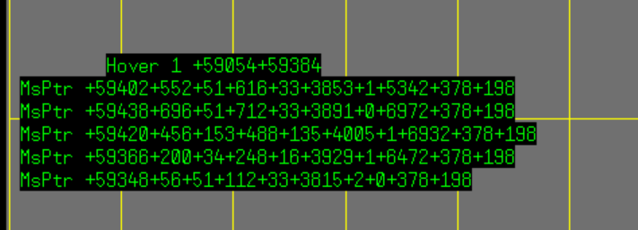
Setting breakpoints I realized, that the screen-routine stalls indeed and finally I realized, the DAT section of the screen process is corrupted.
This is data dumped when OK:
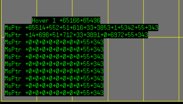
and this is when something goes wrong:
I use Propeller Tool 2.9.3, but had the same result using the current pnut
OK: could be, I use word pointers, and that is just not enough using more than 64K! And the problem arises obviously the moment, the local data is stored at higher memory addresses
OK, this was the minimal program, that didn't work. "dirb and outb are registers in the interpreter" Does this mean, they can no longer be used for I/O? I used "mov outb" in assembler, what works like I'm used from the P1.
Pintoggle did what it should, my original task is to set a trigger and reset it, so I tried "pinhigh() and pinlow()", what also toggles the pin, so I can move it to the right places. Thanks for helping out.
I think the meaning of something like outa[N] changed from "Nth bit of OUTA" to "register[OUTA + N]" in Spin2, because there is a proper bit access operator (that would be OUTA.[N]).
Jon is 100% correct in that there is almost never a reason to directly touch the OUT/DIR/IN registers, especially not from Spin2.
(The "almost never" case being where you want to write multiple bits to pins at once and using the streamer to do it isn't possible/appropriate, so you'd do SETBYTE/MUXQ/etc on OUTA/OUTB)
Does this mean, they can no longer be used for I/O?
Spin2 has better direct pin control than Spin1 so some mechanisms used in the P1 no longer apply to the P2; this instance being an example. It's important to remember that dira[] and outa[] as used in the P1 looked like direct register manipulation, but under-the-hood required a bit of work creating the mask(s) required by the PASM1 code and applying them appropriately. Spin2 and PASM2 are much friendlier for IO control.
Playing with a touch screen using "Cluso's Color LCD Demo with optional Touch Support V3.0" I realized, the touch screen I use (standard display, 320x240) is very noisy in the y-coordinate. The HitButton process then returns a false result, resulting in strange transitions in a state machine. As a work around I call the function 4 times and average the values, limit the hit-window of the button, and still, some sporadic glitches occur. Anyone worked with a touch screen more reliably? (using a P2)
I use the Nextion programmable touch screen displays for work and personal projects. It costs a little more, but is a self-contained unit that uses a simple serial connection to the Propeller.
When I had to choose between a touch screen at a fair price, and a cheap touch screen that promised a lot, I decided for the promising one. Now I have to stand this. OK, step by step finding the weak points and switching over from a IF/THEN solution, ending in a maze, to a state machine of 9 states, I ended up in a 2-states state machine including some if/then.
I'll now integrate the touch interface into my control application and give a report, as it runs.
Ah, right. Yeah, at work, the boss picked up a cheap but still well built stepper drive produced by a large Chinese brand ... and on paper it looked the perfect solution. It has two modes of operation, although that wasn't clear from the datasheet. It can be used as a speed controller with 0-10V + direction + go inputs. Just what we wanted. And this works but it needs a lot of wiring including an extra 0-10V module that we'd run out of, not to mention PNP->NPN relay inversion for the direction and go inputs.
However, it also listed Modbus RS485, which I expected to be a serial set of commands for the same ... Turns out this only provided a dosing mode. Like cut-to-length operation. There is no ability to adjust speed on the fly, so is useless to us. It would've saved a lot of wiring if it worked.
There is no way around the smart pins. Next task: adopt an incremental encoder. There is a quadrature counting mode, I will look for examples and it should work. One short question ahead: is there a way to use the index signal to reset the counter? Alternatively I have to look for the index just once and then handle the over- / underflow manually.
Edit: Found some info in the hardware manual, chapter smart pins. Looks we can measure speed, have to study the docu..


Comments
Forget the first MOV, and ALTS's D operand is meant to be the index.
'Update pattern here alts PatIdx_, #PWMPatt00 ' PatternIdx added mov PattCurr, 0-0As long as the pattern table is in the cogram (of the same cog that executes the code), the ALTS approach should work. I would write it like that:
        alts     PatIdx_, #PWMPatt0   ' PatternIdx added to pattern table addr
        mov      PattCurr,  0-0
Andy
OK, I was close, just not close enough! Now it works as expected. Nothing like the Prop around !
Just a reminder that CANONICAL Spin2 (that is, compiled by PNut/Propeller Tool/Spin Tools) can do assembly testing without invoking a separate cog. I've never used ALTS but think it will be useful in an upcoming project so I took Andy's suggestion and wrapped it into an inline test. It works as intended. Thanks, Andy!
pub demo_alts() org mov pr0, #0 .loop alts pr0, #Fib0 mov pr1, 0-0 debug("Index: ", udec_(pr0), " Fibo:", udec_(pr1)) waitx ##(CLK_FREQ >> 2) incmod pr0, #9 wc if_nc jmp #.loop ret Fib0 long 0 Fib1 long 1 Fib2 long 1 Fib3 long 2 Fib4 long 3 Fib5 long 5 Fib6 long 8 Fib7 long 13 Fib8 long 21 Fib9 long 34 endInline ASM works in flexspin, too, no need to stress out. Recently a new mode has been added that's even more compatible with PNut (Put
{++opt(!fast-inline-asm)}between PUB/PRI and the method name to enable - other compilers treat this as a regular comment)Lol, that might be a little overkill. Jon was just saying he hasn't tested using Flexspin so can't speak for it. His example assembly will compile in just fine without special controls.
The main reason Eric added that full assembler compatibility switch was to provide compile-time cogRAM allocation warnings for two of my chunky Pasm2 Fcache'd routines that use big RES directives. The default assembler can't do the calculation to give a warning.
Coming out with the next question: the smartpin modes are very nice, as I suppose ;-) and now I have to use the ADC the way I'm used the P1: read the ADC counter at any time and determine the number of counts form successive reads at certain times by subtraction. If for example I read the counter 3 times 100 µs apart, the wait for 1 ms to read another three values, I can see, if the signal changes a little.
I have to figure out, if this is possible...
Is it as simple as using "RQPin" ?
I think there is no "free running" mode that behaves exactly like the P1 did. But there are a lot of possible tricks. If you need to sync the ADC sampling window to a PWM you could probably use the Goertzel mode and "abuse" the weighting table to generate seperate sampling windows for the high and low phases.
Or you can use one of the SINC filtering modes with a low sampling period and add a number of samples together.
Mind that the ADC low-level pin mode and the ADC smart mode are independent of each other. The former generates a bitstream that's integrated and sampled by the latter. You could select the ADC pin mode with one of the counting smart modes to get a P1-style thing. I think, anyways, haven't tried it to see if there's a gotcha.
Certainly can, Sinc1 filtering is the Count-Highs mode:
pinstart(<pin number>, P_ADC_1X | P_COUNT_HIGHS, <sample period>, 0)For totalising counter mode just set the sample period = 0, so then it's up to the software to diff.
PS: Silicon Manual has it named as %01111 AND !Y[0] = Count A-input highs
@evanh, that shows good results when I run a first test. Now I have to do is in ASM and it looks, the smart pins are smarter than me ;-)
OK, I have the first conversion running! The signal is way better, than what I'm used to know from the P1! Thanks to all that took part in the development of this great chip!
All to do: set up the ADC and later read and calculate the difference!
' setup ADC Pin 43 Shun
                fltl    pinAdcSh                      'set pin to ADC mode
                wrpin   adc_modes,   pinAdcSh
                wxpin   #0,          pinAdcSh         '#0 is 1-clock
                drvl    pinAdcSh                      'start pin
rdpin Sh_Val0, pinAdcSh ' Read ADC sub Sh_Val0, oldValu ' determine increase of counter add oldvalu, Sh_Val0 ' update to current counter valueThat's it.
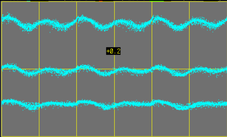
And you will have very nice signals from a 50 kHz source!
I'm working with a data buffer:
The app works as expected with a buffer size of 4096, but no longer with 8196. While I'm looking deeper into this issue: Is there any limitation of the Array size (I can not imagine this to be the case)
Why why don’t you show the code that deals with head and tail pointers?
This is a very primitive version. One COG reads the ADC at 50 kHz and writes data to the hub until the buffer is filled. A flag is set. A plot routine plots the buffer and resets the flag after completion. I just want to be sure, that larger arrays up to the memory limits are possible. Ringbuf1 is defined just to protect the memory if there is any leak, but this buffer is OK, as far as I have tested. Will be out of office tomorrow and dig into it on Wednesday.
If you're doing any left-shifts or multiplies, those can easily lose the most significant bit as the initial value is increased. MULDIV64() is available for re-scaling without chopping the tops off.
One bug found: a missing character when two variables share the "same" name. So the answer is "Yes, your arrays can use all the memory available". The bug again was sitting in front of the screen ;-)
Next: I used a terminal to start the program, which was boring and so I did an auto-start. Accidentally I realized, larger array worked, it was the terminal program that stalled for unknown reason....
Debugging the issue with Array size:
I have a rather complex program using 7 COGs, the original P1 version worked for more than a decade, limited by space and speed. This program is moved to the P2, needed only little modification, some systematically, others more difficult to find. Now I face this situation:
There is a set of buffers, normally 1k of LONGs. Now, that the functions mostly work, I tried to extend the buffer and it came to a stall of the display process. Carefully adjusting the buffer size I could find the limit. Adding another line of code stalled the program again, reducing buffer size brought the program to life again.
Setting breakpoints I realized, that the screen-routine stalls indeed and finally I realized, the DAT section of the screen process is corrupted.
This is data dumped when OK:
and this is when something goes wrong:
I use Propeller Tool 2.9.3, but had the same result using the current pnut
OK: could be, I use word pointers, and that is just not enough using more than 64K! And the problem arises obviously the moment, the local data is stored at higher memory addresses
YES, that did the job!
This is strange:
  clkset (clkmode_, clkfreq_)
  dirb[7] := 1
  repeat
    outb[7] := 1
    outb[7]:= 0
I expect Pin 39 to toggle: but he is reluctant!
If you're going to do it in Spin2, why not be obvious about it?
  repeat
    pintoggle(39)
dirb and outb are registers in the interpreter.
This is what I get when running the P2 at 200MHz.
OK, this was the minimal program, that didn't work. "dirb and outb are registers in the interpreter" Does this mean, they can no longer be used for I/O? I used "mov outb" in assembler, what works like I'm used from the P1.
Pintoggle did what it should, my original task is to set a trigger and reset it, so I tried "pinhigh() and pinlow()", what also toggles the pin, so I can move it to the right places. Thanks for helping out.
I think the meaning of something like
outa[N]changed from "Nth bit of OUTA" to "register[OUTA + N]" in Spin2, because there is a proper bit access operator (that would beOUTA.[N]).Jon is 100% correct in that there is almost never a reason to directly touch the OUT/DIR/IN registers, especially not from Spin2.
(The "almost never" case being where you want to write multiple bits to pins at once and using the streamer to do it isn't possible/appropriate, so you'd do SETBYTE/MUXQ/etc on OUTA/OUTB)
Spin2 has better direct pin control than Spin1 so some mechanisms used in the P1 no longer apply to the P2; this instance being an example. It's important to remember that dira[] and outa[] as used in the P1 looked like direct register manipulation, but under-the-hood required a bit of work creating the mask(s) required by the PASM1 code and applying them appropriately. Spin2 and PASM2 are much friendlier for IO control.
Playing with a touch screen using "Cluso's Color LCD Demo with optional Touch Support V3.0" I realized, the touch screen I use (standard display, 320x240) is very noisy in the y-coordinate. The HitButton process then returns a false result, resulting in strange transitions in a state machine. As a work around I call the function 4 times and average the values, limit the hit-window of the button, and still, some sporadic glitches occur. Anyone worked with a touch screen more reliably? (using a P2)
I use the Nextion programmable touch screen displays for work and personal projects. It costs a little more, but is a self-contained unit that uses a simple serial connection to the Propeller.
With a touch screen it's like with politics: you have to dance with the ladies, that joined the party ;-)
That might be the most left-field comment I've seen! You're gonna have to explain that one Erna.
When I had to choose between a touch screen at a fair price, and a cheap touch screen that promised a lot, I decided for the promising one. Now I have to stand this. OK, step by step finding the weak points and switching over from a IF/THEN solution, ending in a maze, to a state machine of 9 states, I ended up in a 2-states state machine including some if/then.
I'll now integrate the touch interface into my control application and give a report, as it runs.
Ah, right. Yeah, at work, the boss picked up a cheap but still well built stepper drive produced by a large Chinese brand ... and on paper it looked the perfect solution. It has two modes of operation, although that wasn't clear from the datasheet. It can be used as a speed controller with 0-10V + direction + go inputs. Just what we wanted. And this works but it needs a lot of wiring including an extra 0-10V module that we'd run out of, not to mention PNP->NPN relay inversion for the direction and go inputs.
However, it also listed Modbus RS485, which I expected to be a serial set of commands for the same ... Turns out this only provided a dosing mode. Like cut-to-length operation. There is no ability to adjust speed on the fly, so is useless to us. It would've saved a lot of wiring if it worked.
There is no way around the smart pins. Next task: adopt an incremental encoder. There is a quadrature counting mode, I will look for examples and it should work. One short question ahead: is there a way to use the index signal to reset the counter? Alternatively I have to look for the index just once and then handle the over- / underflow manually.
Edit: Found some info in the hardware manual, chapter smart pins. Looks we can measure speed, have to study the docu..