

A DAC that can drive a motor?
 mpark
Posts: 1,336
mpark
Posts: 1,336
Just idle musing on a Sunday morning...
Instead of using PWM to control a DC motor's speed (by faking a variable voltage), wouldn't it be neat to use a digital-to-analog converter to drive the motor with an actual variable voltage? Presumably the DAC's output would have to be beefed up somehow.
Maybe there is such a device? Maybe not, because it's a terrible idea? Happy to be educated.
Comments
The reason for not doing it is terrible efficiency.
A power opamp -well cooled- will do the trick.
It is possible to have both worlds. You can have the efficiency of switch-mode power conversion while still delivering that power down the cable as smooth analogue - And clean power transmission becomes increasingly valuable as the power increases. It just takes having the right sized filter sat in between.
This is in fact how 1-bit audio DACs work. They take advantage of having a huge frequency ratio between the switching frequency and the modulated analogue frequency range. It allows the filter to work super clean. However, this all still happens at low power and the final audio power circuits stay as low efficiency analogue. The purpose here is not for efficiency but rather to retain signal integrity over many transports.
Now, having touted all that. There is an efficiency trade-off at higher switching frequencies too. The transistors have dv/dt limits of there own so they struggle to handle both high frequency and high power together. They get hot and lose efficiency. The usual workaround is to lower the switching frequency. This then places more burden on sizing the filter correctly.
PS: The newer Silicon-Carbide fabricating materials is used to extend the working range of switching power transistors. As does the IGBT transistor type.
PPS: I've never learnt how to size a filter right. My skill stops at basic R-C low-pass filers.
With small DC motors though, the usual method is forget about the filter and just feed the switcher output direct to the motor. The motor is the filter. Use a shielded cable and you'll be fine.
What I would advise doing is adding optocouplers to the inputs of the motor drive. So then there is no possible fault path back from the motor supply to the control supply. Or at the very least inline resistors, clamping diodes and strong local ground plane.
A class D amplifier might do it ...
https://en.wikipedia.org/wiki/Class-D_amplifier
Linear amplifiers for motor control do exist
I was considering the Class D approach, myself, some time ago.
Interesting link, @Mickster even if the text layout is a little weird. Paragraphs displayed as two columns?! Who does that?
Yeah, now you mention it.
They have some neat products, the last thing I need is more inspiration because I'm overloaded already
I am interested in a linear amplifier for small motor control though and have looked many-a-time for a quick, low-cost solution but only ever found this high-end stuff.
Let us know if you decide to do something
Not sure if this direct link will work because I had to sign-up
So here's the sign-up page
That direct link worked without sign-up, thanks! Most of it is over my head, though. I'll just stick to PWM")
This is more along the lines of what I've been looking for
Nice! So simple, emitter follower is best way to use BJTs. Prevents saturation. That's why IGBTs are so successful.
It's simple, but struggles to get near the rails.
A common alternative is to feed the opamp power into the bases, with RBE resistors scaled so the BJT are just off under normal bias, and a moderate load resistor on the output, then gives drive base current.
There is some inbuilt current limit, via the load resistor and chosen BJT HFE curves
Use an opamp with good PSRR and stable Icc.
Can also use MOSFETs but their VTH variation is more of a problem.
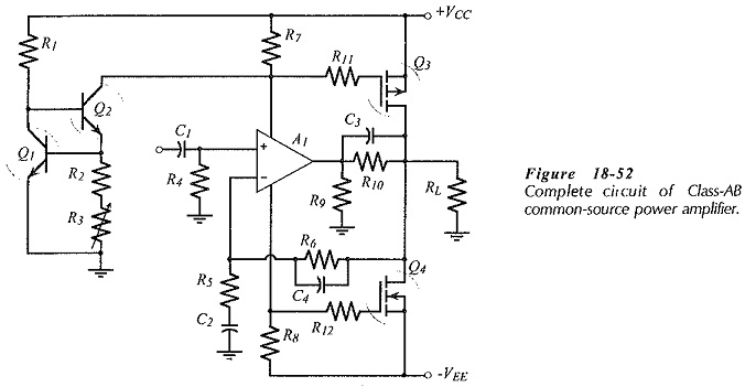
Addit: here is a MOSFET version
R3 sets IQ, and Q1 thermally tracks Q3 & Q4, but only somewhat loosely due to thermal coupling difficulties, thermal delays, and BJT's do not track MOSFETS %Vth/'C wonderfully.
An advantage of these common collector / common drain designs is the power parts can directly bolt onto the same 'live' heatsink.
I wouldn't call that much of an issue. It is a linear amp after all.