

Hack of the day: step/dir signal diagnosis tool
 ManAtWork
Posts: 2,334
ManAtWork
Posts: 2,334
A customer of my CNC controller complained about his machine making jerky noises during the homing procedure. He suspects that the servos are given discontinous velocity commands which results in acceleration spikes.
I simulated this here by running the controller with exactly the same parameters as on his machine. But of course, with only the bare motors connected without any load. The inertia is much lower than with the big and heavy machine and I can't tell for sure if there are acceleration spikes or not. I can log position coordinates of the communication between the PC and the controller (P1) and I can't see any discontinuities or suspicious values for velocity or acceleration. But that doesn't prove that the output of the controller to the servo is correct.
So I took the soldering iron and hooked up some du-pont wires to tap the step/dir signals and route them to a P2 board. This 20-something-liner displays the velocity calculated from the step signals in a DEBUG scope window.
CON
  _clkfreq = 200_000_000
  _xtlfreq = 25_000_000

  pinStp = 0
  pinDir = 1
  modeStp = P_REG_UP_DOWN + P_PLUS1_B
  period = 1_000_000  ' 5ms intervals

PUB main() | a

  debug(`SCOPE StepDir SIZE 1000 220)
  debug(`StepDir 'Velocity' -100 100 200 10 15 MAGENTA)
  debug(`StepDir TRIGGER 0 0 10 230)

  pinstart (pinStp, modeStp, period, 0)
  repeat
    repeat until pinr (pinStp)
    a:= rdpin (pinStp)
    debug(`StepDir `(a))

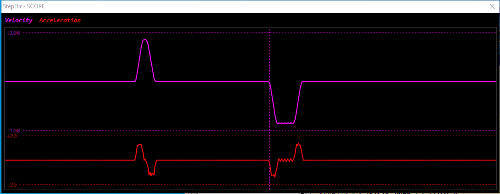
I plan to add a step totalizer count to debug lost steps and min/max displays for velocity and acceleration.
Comments
BTW, does anybody know how the offset value for the TRIGGER feature is supposed to work? I thought it was an offset in pixels so width/2 would center the trigger line horizontally. But greater values shift the line to the left. 230 gives something near the left end of the window, 130 near the center and 0 is on the right side.
blue cable comes from the controller, green cable goes to the servo
Arrgg. I hate it when the customer is right and the problem is my fault. There is actually an abnomally in the velocity command to the servo.
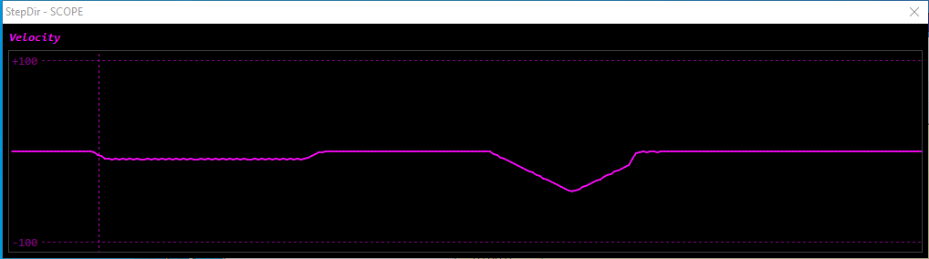
The bathub curve on the left side is the axis slowly inching away from the homing switch until it triggers. The inverted pyramid on the right side is the "safety distance offfset" move after the homing procedure. The last bit of the decelleration ramp is missing. It seems like just before the servo comes to a complete stop a "quasi" emergency stop is triggered which uses a much higher acceleration.
You don't use the encoder index pulse?
Craig
Short answer: no.
More detailed explanation: Yes, I have used the index pulse once or twice for homing. But I don't build machines myself. My customers use all different types of drives. Most of them don't have a "real" index pulse. Some of them are stepper drives which don't have encoders at all. Others use servos with absolute encoders of resolvers which have an "emulated" index output. Telling the customer how to connect the emulated index and troubleshooting it when it doesn't work is more complicated than simply telling them to use a better homing switch with higher precision.
If that $%&§# EtherCat thing would be working I could just use the internal homing procedure of the drive which usually supports the index. Or use multiturn absolute encoders and get rid of the homing at all.
Now, the problem is solved, but it was a hard nut to crack.
I thought that it has something to do with the homing procedure because the jerky movement often happened at the first move after homing. But the actual cause was a sort of "rounding error". The motion profile generator uses timeslices of 5ms for the position vector buffer and 1.25ms for the interpolator. When jogging "natural" distances of multiples of 1mm or multiples of 0.1mm and so on the total distances usually fit into equally spaced pieces in the vector buffer. But if the distance is an "odd" number (for example 5.116mm) the remaining delta position for the last vector is smaller.
The trajectory planner alwqays needs to look ahead to know when to start a decelleration ramp so it exactly hits the destination point. For some "unlucky" numbers the calculation of when to start the ramp was slightly off. All calculations use integer numbers so there can always be rounding errors and I have to re-caclculate the exact decelleration for each time slice so they don't sum up and the destination point es hit exactly. But if the error is too large this can cause the acceleration to overshoot and oscillate around the ideal line for the ramp. Now, the cut off distance of the last vector buffer is taken into account for the remaining distance for the ramp and the velocity profile is perfectly smooth.
Apart from homing, I use the index to check count integrity...must always be a multiple of counts/rev.
Craig
So far I tried to avoid that because I was afraid of triggering false alarms. What is the best way to reliably monitor the index pulse? The index is normally gnerated by some logic gate network inside the encoder. The actual optical index mark is much wider than a single quadrature state. So the index pulse from the optical sensor is ANDed with the quadrature state 00 or 11 to make the index output. This leads to a tiny delay so that the index usually goes active right after a quadrature state change and ovelaps a bit into the next state.
So the best method for detecting the index is to sample it in the middle of a quadrature count state, right?
Yeah, I don't like to encumber the counting logic or use any more clocks than absolutely necessary. I always have a fast, deterministic loop running in another cog. When the AND-ed input goes high, snapshoot the current count value and compare:
It was good to read your thoughts re: BiSS, SSI, etc. I sometimes worry that I'm behind the times by sticking with incremental encoders but I can always source these things within 24hrs.
Craig