New HW project - P2 Bull Ant
 rogloh
Posts: 6,311
rogloh
Posts: 6,311
I've started a new P2 hardware project I've had kicking about in my head for a while now.
The history:
Some time back I used the first Topfield HD PVR (Korean brand) which as usual for early adopters was rather buggy and thankfully it has been upgraded with a better model I've since purchased. But rather than just junking it I kept it stored away as I always quite liked its enclosure and thought it might be put to good use some day. Turns out that was correct as this is pretty much an ideal enclosure for a P2 for doing A/V related projects as it contains the full selection of video output connection types which the P2 can readily generate:
- HDMI
- VGA
- Component YUV
- S-video
- Composite RCA
It also contains a similarly useful set of analog and digital audio output capabilities.
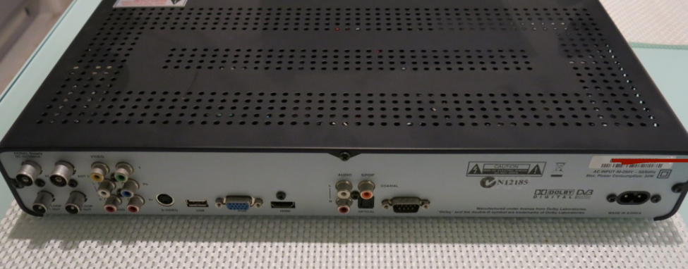
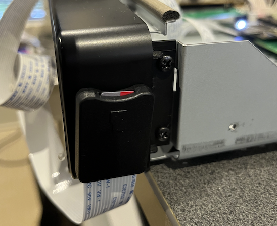
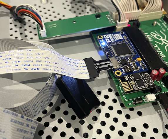
It contains a USB-A port and DB9 serial port and other rear panel holes cutout for a dual tuner which could be repurposed. It includes a 32W power supply which can power the system and the VFD front panel with the different voltage rails required. The front panel has its own micro (8052 based IIRC) which communicates serially with a host and can be instructed to light up all alphanumeric and indicator segments independently on the display. It also includes a battery backed RTC and an IR sensor and decodes and outputs NEC format IR codes from its original remote control. Plus it has some signal output lines which can wake up the system from the front panel power button or from an alarm schedule as well as power it off when in standby. There are four other panel buttons as well which are detected and signalled serially to the host CPU (which in this project as you'd suspect will be a P2). I've already had success in communicating with this board using a P2 previously as shown in this picture.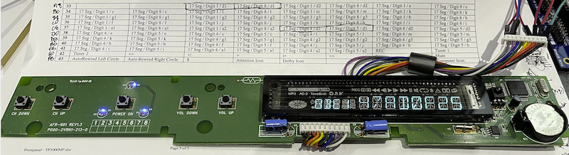
The design:
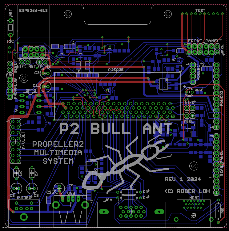
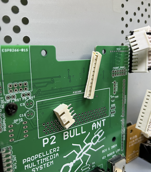
In the last couple of weeks I have designed a motherboard for a P2 Edge which I've called the P2 Bull Ant. If you are not from Australia, you might like to know that a Bull Ant is one of our rather nasty and large ants (~25-35mm long) that is seen just about everywhere here and is aggressive and has a powerful bite and sting, speaking from personal experience a long time ago. Can hurt for hours if you get a full dose once it really latches on to you, and hopefully you're not allergic to it either.
My P2 Bull Ant PCB is a versatile system board that should allow all types of video outputs from the P2 as well as a few other goodies. Namely:
- Optical TOSLINK digital and coaxial S/PDIF audio output
- 24 bit stereo DAC outputs from an I2S source - 44.1 & 48kHz clock selectable
- RC filtered analog audio outputs (which can be mixed with the 24 bit DAC output via jumpers, as well as kept seperate on their own independent output RCA jacks)
- Front panel control including optional wake/shutdown/reset
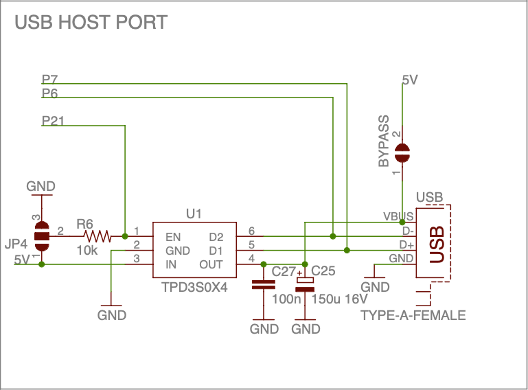
- USB host capabilities with software controlled power on/off of 5V USB power
- Serial control via RS232 Tx/Rx signals (wired as DTE)
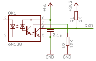
- Midi TX & optocoupled RX circuitry built in
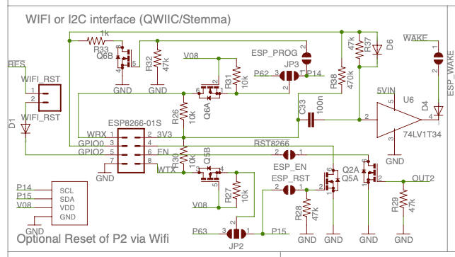
- Wifi (via ESP8266 controller in ESP-01S package)
Like the front panel the Wifi module is independently powered and has been designed to support optionally waking and/or resetting the P2 depending on its own firmware control of GPIO pins. It has its own dedicated TX/RX signals going into the P2, but they can also be overridden with solder jumpers to use P62/P63 instead of the original pair of P2 IO pins in the case of desiring P2 image downloads or upgrades over Wifi.
If Wifi is not used (or instead gets assigned to P62/63) the otherwise spare dedicated pin pair can be used with an I2C header (Stemma/QT compatible), or alternatively to shutdown/reprogram the Wifi module itself initially (via solder jumpers).
A PropPlug header and external reset header is provided, along with a manual "Force Wake" button header in case things go awry and the front panel otherwise hangs while in shutdown, preventing powerup.
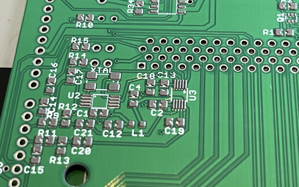
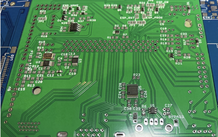
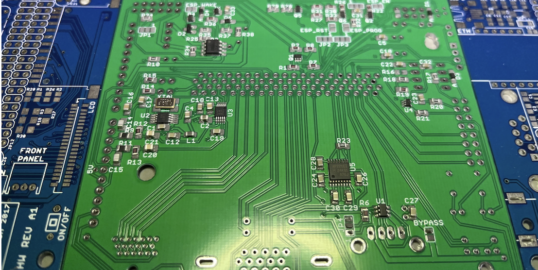
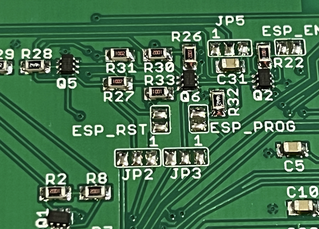
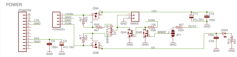
That basically summarizes the hardware. The zipped schematic is attached and layout is shown below. Some component values may be subject to change if I find issues.
P2 I/O pin allocation:
This board uses a P2 Edge with PSRAM so not all I/O signals are available. The board's HW signals are allocated to the P2 I/O in the following way.
- P0 - composite video
- P1 - Blue/Cb
- P2 - Green/Y
- P3 - Red/Cr
- P4 - Y Luma for S-video
- P5 - C Chroma for S-video
- P6 - USB D-
- P7 - USB D+
- P8 - RS232 Tx
- P9 - RS232 Rx
- P10 - MIDI Tx
- P11 - MIDI Rx
- P12 - Front Panel Tx
- P13 - Front Panel Rx
- P14 - Wifi Tx
- P15 - Wifi Rx
- P16..P20 - VGA signals
- P21 - USB Power Enable
- P22 - Left Audio
- P23 - Right Audio
- P24..P31 - HDMI signals
- P32 - I2S SDIN
- P33 - I2S LRCLK
- P34 - I2S SCLK
- P35 - FSEL (44.1/48kHz) output select to clock synth
- P36 - I2S MCLK
- P37 - Clock synth output to P2 input
- P38 - TOSLINK Tx [also LED on P2 Edge]
- P39 - RCA Coaxial output [also LED on P2 Edge]
- P40..P57 - [PSRAM on P2 Edge]
- P58..P61 - [SPI Flash/SD card on P2 Edge]
- P62 - P2 Tx
- P63 - P2 RX
Applications:
This hardware could be used for several applications, such as a video game system with Wuerfel_21's and other's emulators. It could become an audio streamer to a hifi system sourced from an SD card filesystem or even potentially via Wifi. It would be useful for my video driver development and also includes the PSRAM from the P2 Edge. With the MIDI connections and high quality audio outputs it could be handy for a music synthesizer project or a MIDI sequencer to control MIDI equipment from the P2. I expect it should be quite versatile. Also being enclosed it is far more rugged than a standalone board on a bench with other adapters hanging off it like when using the P2 Eval or P2 Edge breakout boards.
Construction:
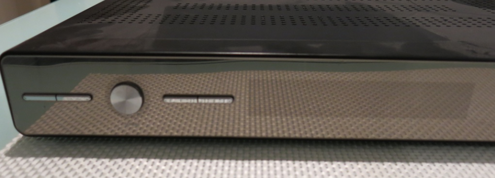
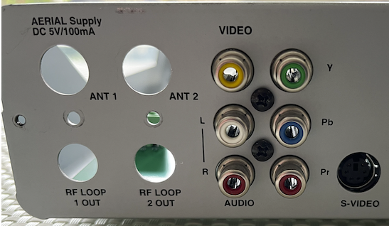
Here are some pictures of the original enclosure and later my changes.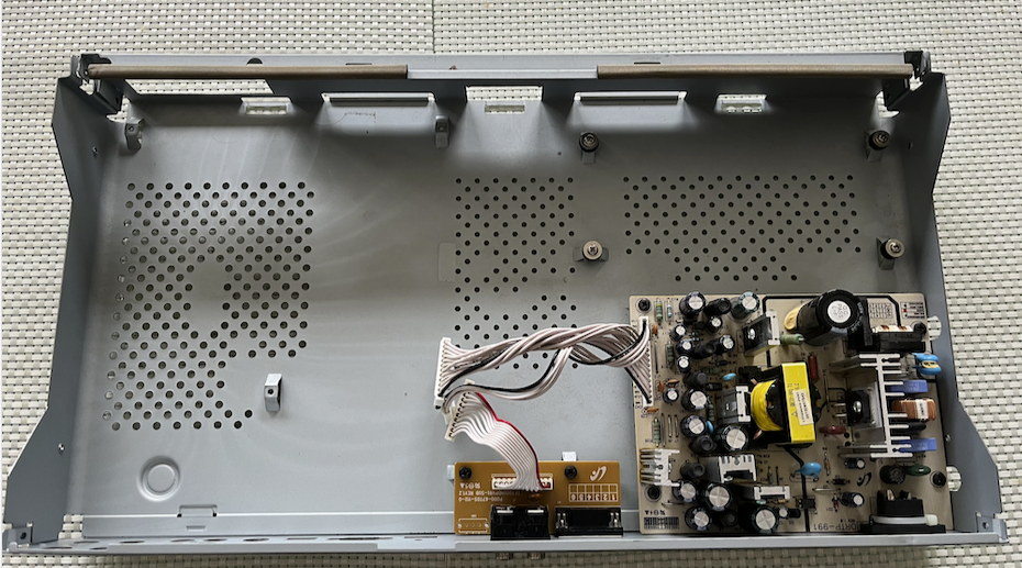
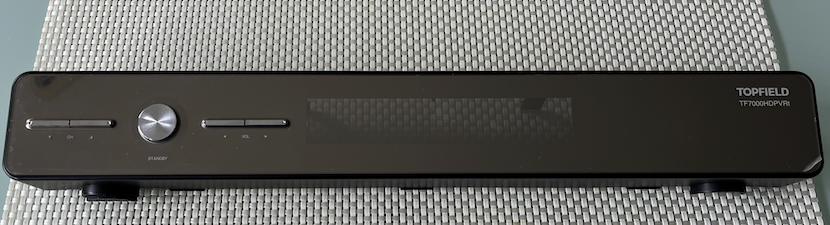
LOL, it still needs the clear protective sticker to be removed which I only even noticed when its edge frayed - this is good as it will protect the front panel while I work on it.
This VFD panel sits behind it.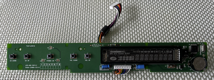
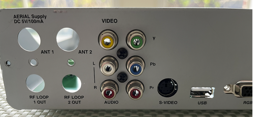
I will need to reuse the 6 way RCA jack from the original donor PVR motherboard as this is an uncommon part I was unable to find searching around online that would perfectly match up with the order of signals printed on the panel (although I do imagine it is available somewhere - likely only in large quantities). Tubular kindly helped out by desoldering the bulky connector and despite being slightly worse for wear afterwards we managed to salvage it for reuse. This is retained in place with two screws on the rear panel so it still perfectly aligns nicely with the holes.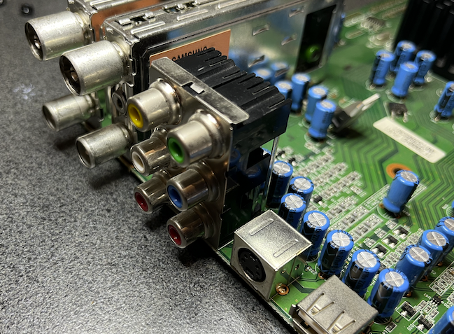
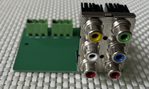
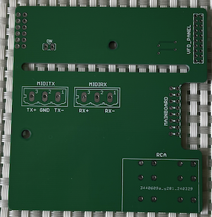
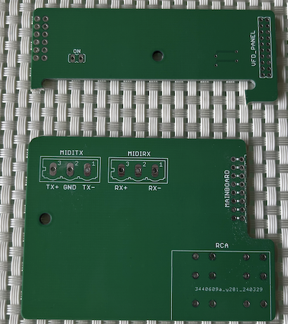
I split my P2 system into two interconnected boards as my PCB CAD software is board size limited and 10x10cm or smaller boards are very cheap to prototype while larger ones quickly escalate in price. The P2 Bull Ant is the main board and the smaller board just allows access to the RCA jacks as well as providing some headers to the MIDI connections. At the last minute I also included an upper snap off section on the smaller board to potentially extend a 2mm connector closer to the front panel cable which is rather short and may not reach it otherwise, although in the end if I am lucky it may not be required (TBD).
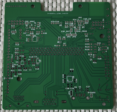
The boards arrived yesterday and seem decent. I also obtained a stencil for the SMD parts which are populated on the bottom layer.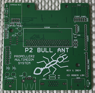
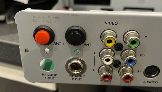
Fitment worked out nicely and the connectors thankfully lined up properly with the rear panel as seen in the pictures.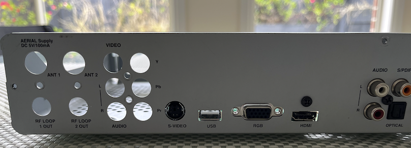
The spare top holes on the left of the rear panel could be used for MIDI DIN5 sockets if they are installed sideways. They just need enlargement (I have step drills) and another small hole drilled for the connector's second mounting bolts. Not sure if internal or external mounting would be best. External will cover the hole if it is roughly cut but internal mount can look good too. The lower two holes could suit pushbuttons for reset and wake inputs if I add some washers or a suitably sized and a relabelled cover plate.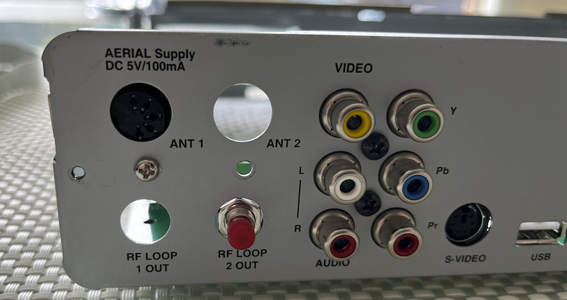
I noticed that one PCB mounting hole was a little bit off near the Wifi module (not sure why as I'm usually meticulous in measuring this stuff) but I can drill it out manually to fix it or just use other holes for mounting to the enclosure using some extra standoffs.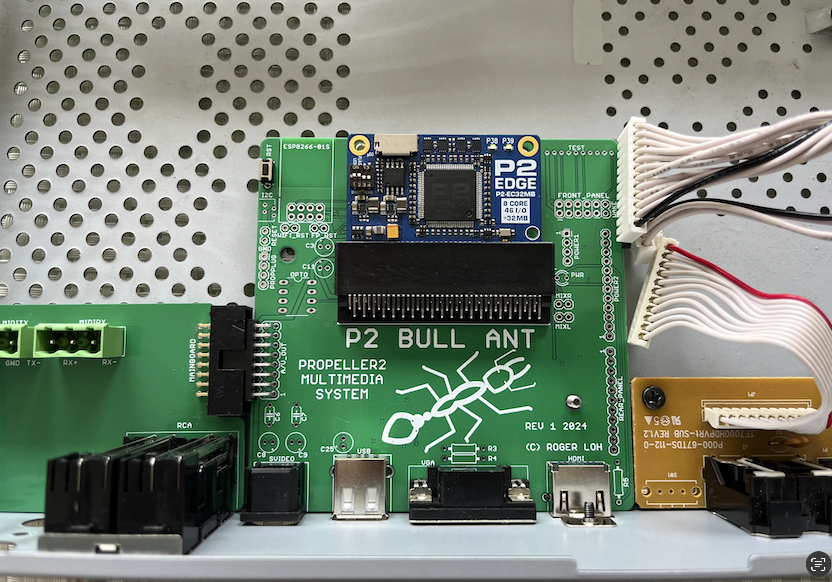
I also may ultimately want to embed a PropPlug inside the system and bring out micro-USB via a panel mounted USB socket above the DB9. A microSD extender cable was also purchased to experiment with and determine if the P2 can transfer data over this length of cable to read/write files on the microSD card. Ultimately if it works out it could be mounted to the front panel if I'm willing to carefully cut in the plastic and I figure out a thin bezel or something nice to surround it. :-) There is a bit of room in the front of the enclosure for mounting - looks like it was originally designed perhaps for a smart card reader to go here or something else for satellite/pay tv conditional access etc.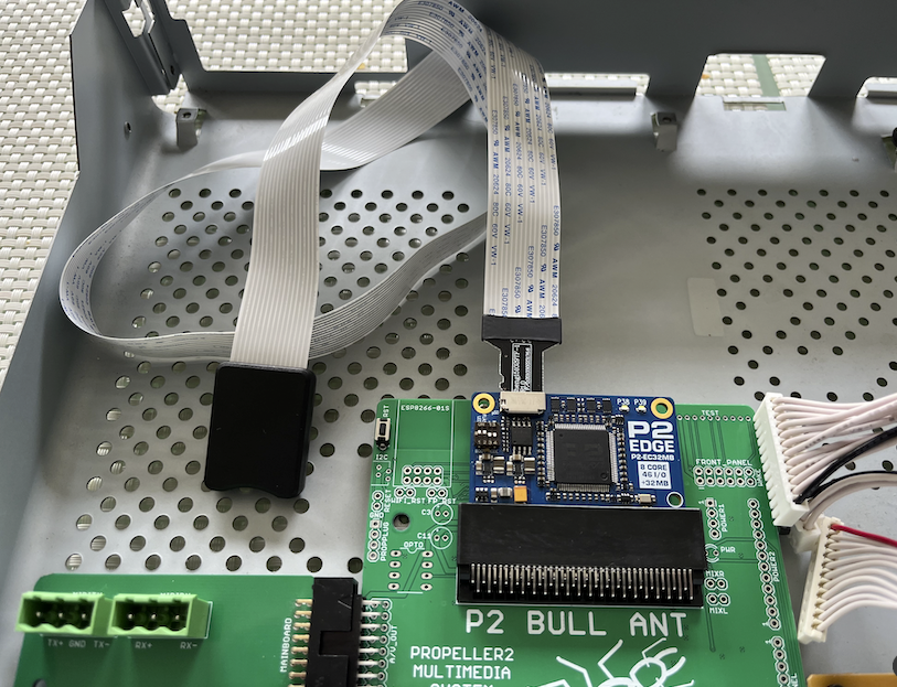
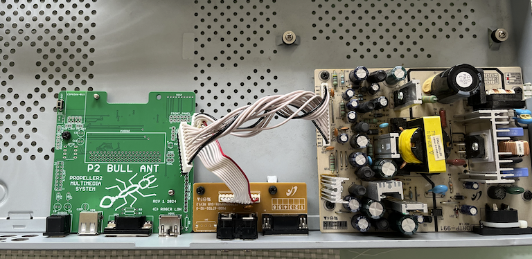
The system is powered from the original PVR power supply via pin headers that mate with the existing cable harnesses. There is also a cable connection to the single sided digital audio and DB9 breakout board that was part of the original PVR and is also retained here.
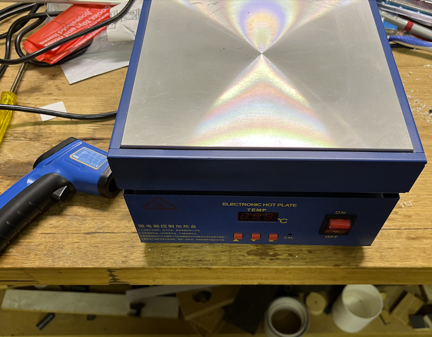
My SMD parts also arrived yesterday from Digikey and I will include more pictures as the project develops and I construct further. I could solder manually but at this point given I ordered the stencil I may as well use my electronic hotplate to solder the board, and hopefully I won't mess it up. I do have enough parts for a second board if needed or if I find problems with the PCB design and need a respin.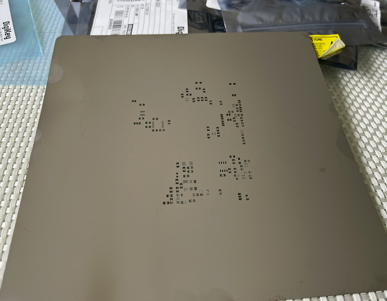
Will post more as I go...
Comments
Nice project!
As you are routing i2s through P2, you could add some nice reverb to convert your room into a great hall.
Yeah the P2 could do all sorts of audio processing. I'm not much of a DSP guy but am sure it would be feasible to use for things like that. Another possibility is to add an optical audio receiver via the two optional Wifi/I2C/spare pins, or maybe take in data via coaxial RCA and sample on the P2 with the ADC (this is currently DC coupled on the existing output jack). You could then in theory read in a digital audio stream and process it. I think it will be handy for experimenting.
Nice one!
Though I'm usually one for more pleasant namesakes.
Thanks.
LOL. That's because you are not from Australia. We're a different breed down here. Maybe my next P2 board could be the blue-ringed octopus then followed up by the stonefish.") There's plenty of choice here.
There's plenty of choice here.
Yeah. I suppose having to walk on your hands to compensate the upside-down-ness makes you stronger.
Didn't think I was going to be able to salvage the original connectors for the internal wiring harnesses so didn't plan on it in the design but with a bit of luck and only minor burns I was able to remove a couple of them from the donor PCB and they survived and still make connection. It's hard to find the exact match for connectors from a product of 15 years ago or so. For one of them I think I still need to use generic 0.1 inch pin headers as the connectors are a bit close together for the original to work there as well. But that's fine as I was planning on doing that all along anyway.
I also found I needed to use the extension board for the front panel as the cable is about 10mm too short to reach in the end, so luckily I designed for that eventuality otherwise some ugly wire cutting would have been needed.
I also fixed up that mounting hole by drilling 2mm further out on the PCB. I have no idea why it was off. Bad eyesight on metal rulers, or a typo in Eagle perhaps. Also that single sided board was pressing up against it and shifted it over a little as well. I can file that edge back a bit which will help.
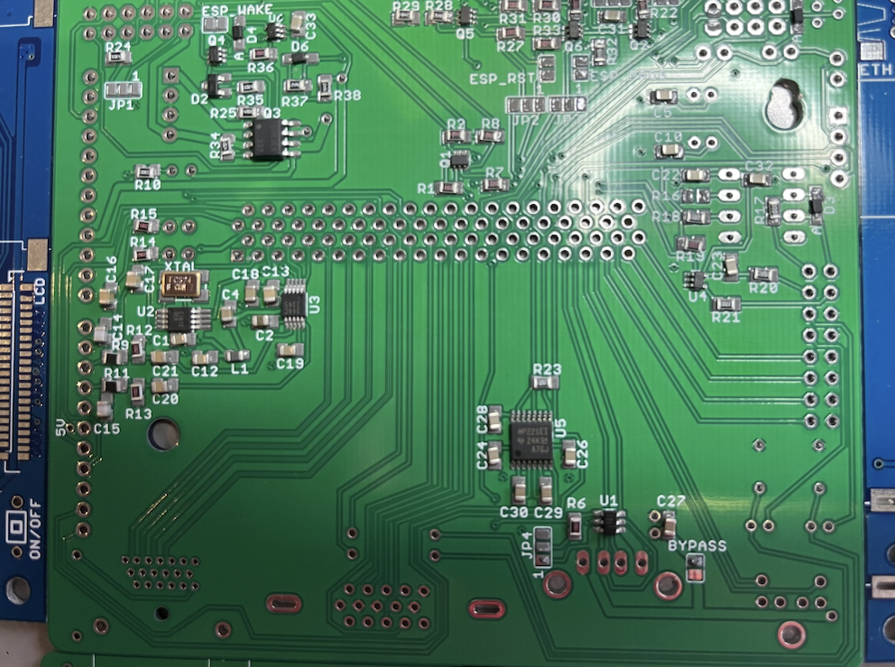
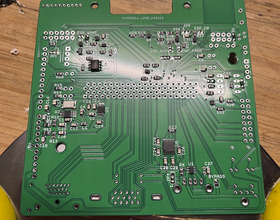
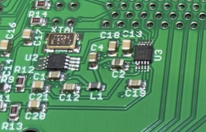
Made some progress today and the SMD components are now soldered. Here's a few photos I took along the way.
Setting up for stencil pasting and manual placement.
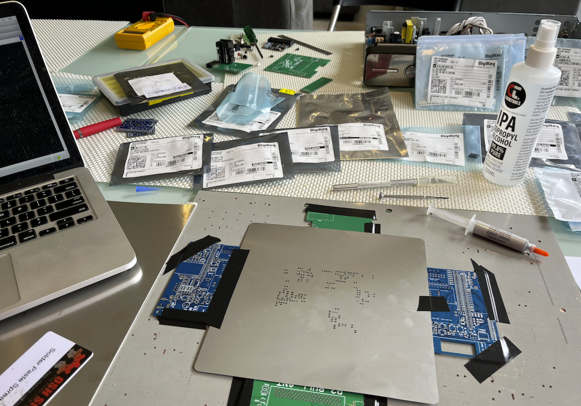
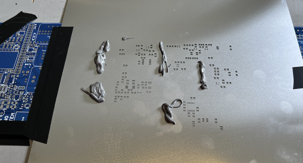
Paste is ready.
Nailed it first time around - that's a first. Probably helped having fresh solder paste to work with.
Placed the semiconductors initially, followed by passives. I figured it was easier to load the tricky parts when there wasn't much on the board already. The 0805 stuff is very simple in comparison.
All parts I want done are down. Didn't smudge it either which pleasantly surprised me. Shaky hands are your enemy.
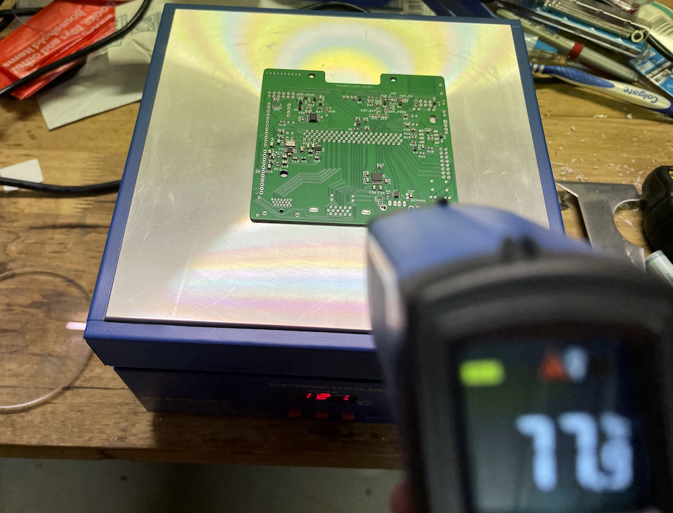
Hotplate setup.
Cooking the board.
Cooldown - had a fan blowing air on the board to speed this up.
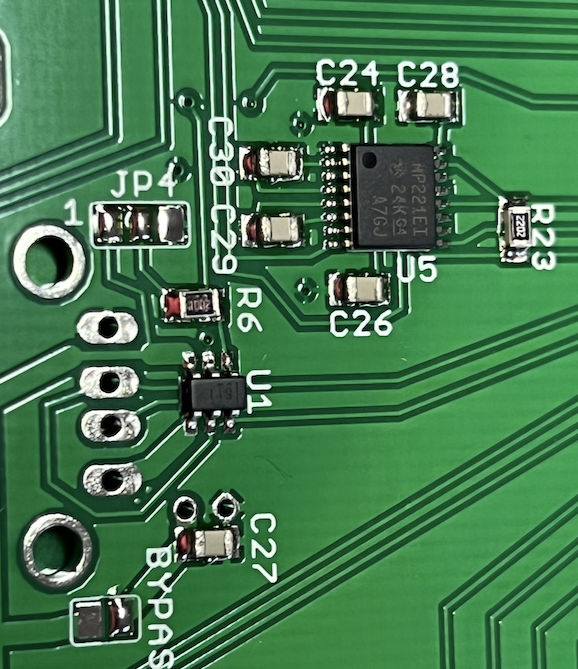
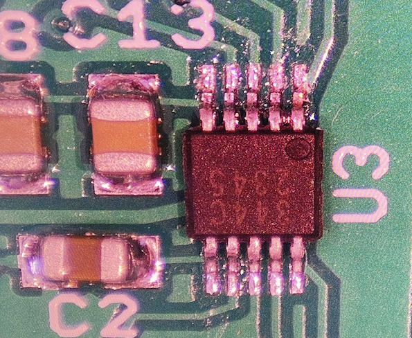
Happy with the result...will check parts under scope later tonight or tomorrow to see what rework is needed. I noticed a couple of bridges on the 0.5mm pitch DAC IC U3 and Q1 was rotated a bit but can be fixed with hot air or iron.
This part isn't too good, though the rest align okay. Q1 as seen on my microscope.
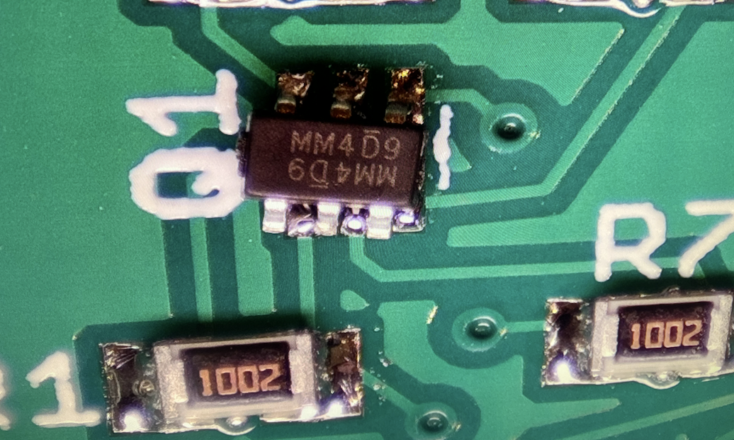
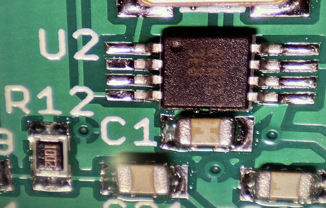
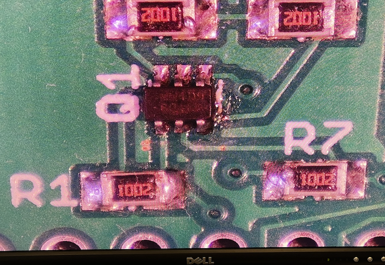
Hopefully these solder joints are okay. This is indicative of the result I obtained in general. Maybe I should touch things up with the iron to ensure everything reflowed fully.
Update:
Fixed the DAC TSSOP and Q1 is at least electrically connected now (it's a bit ugly but whatever).
I like your hot plate setup. I’ve never used a mask for the paste, just did it by hand but that could be really time consuming.
Yeah the hotplate is handy. Got it during the lockdown, wasn't too expensive at the time (~$130 AUD) though more than a toaster oven. Not sure how well calibrated it is but it does the job for me after just watching the paste melt into the shiny metallic state and giving it another 30s or so after that. It doesn't follow the ideal solder profile (takes longer to heat up, and cool down unless you use a fan and remove the board at the peak temp) but it still works for prototyping anyway.
Here's a teardown of this unit. Mine runs at 240V, not 110V.

Metal stencil was cheap at about $7USD IIRC. Well worth it to save the time IMO when you have a board with fine pitch stuff and multiple other components. It gives a consistent amount of solder to all components vs doing by hand.
Started testing today. This P2 Bull Ant is showing good signs of life so far.
Still to test:
Getting control and responses from the front panel. This proves that dodgy Q1 FET rework is ok too as it is part of the serial data path with the 3V to 5V translation into the VFD.
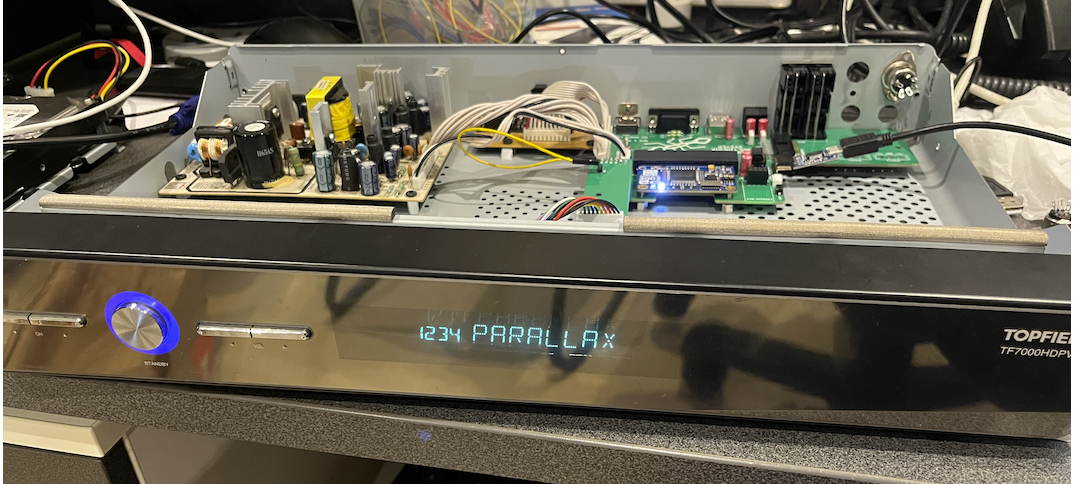
Oh yes, VFDs are a must for any sort of black box that goes under a TV! Such a nice glow.
Just tested digital audio circuitry on the Bull Ant after soldering in final parts needed for that.
1) analog mix to secondary DAC RCA jacks is working when jumper shunts are fitted Used some simple test code from prior work here https://forums.parallax.com/discussion/comment/1546330/#Comment_1546330
2) i2s DAC output is working on both channels
3) audio oscillator frequency rises when 48 kHz is chosen vs 44.1kHz using FSEL pin from P2 - good sign it's switching to higher frequency
4) the Toslink LED is flashing under P2 control. I am only running it at 3.3V for VCC but this can be changed to 5V if required or if this module can't run at 3.3V - some can run with either voltage. LED seems bright enough at this point.
5) S/PDIF coaxial port is connected to rear RCA jack - for now just sent some composite video over this output to test it
Also tested RS232 port transfers in a simple loopback on the DB9 pin 2 & 3 signal pair, working as well.
So basically for now everything on this board apart from the Wifi block is verified as far as simple connectivity goes. Still to connect to some real equipment for true validation of some items but confidence is now very high it will work. Am pretty happy that the DAC stuff is all going as they were some fine pitch parts.
Now need to prepare myself to cut the case for the MIDI DIN5 stuff. I probably should also route the PropPlug's USB cable back through there too so I can close the lid. Could be a while yet before Wifi is fully integrated. I just found the micro USB cable could actually fit through the upper antenna holes so that is something useful too, temporarily anyway.
So I found more useful info on the VFD front panel capabilities in the link below.
https://hackaday.io/project/181070-reversing-topfield-tf5100-pvr-display-module/details
I can now write the time and date to the RTC and also setup a wakeup timer from the P2. Turns out it won’t wake up if it's only 1min away from the set alarm time (too short) but 2 mins away or greater is okay. So this box should be able to boot up the P2 automatically at some scheduled time in the future which could be useful. When the system is in standby, in addition to the current time, a little timer icon is shown on the VFD to indicate that an alarm will wake the system sometime down the track.
Other findings:
The P2 can instruct the front panel (FP) to reboot itself - obviously only useful if running a P2 from flash/SD otherwise it just stops running and hangs for serial download. The FP will pulse an output line high for one second and this will toggle the power state of the P2 Bull Ant board momentarily.
The IR remote can wake up the system when powered off along with the front panel buttons. In fact the system always can seem to power on by itself with a press of the front panel standby button so there is probably no need for a separate "wake" switch as such. I was probably being paranoid there. However what has to happen to be able to shutdown while awake is that the P2 needs to tell the FP to either shutdown when required, or program the panel to enable the shutdown watchdog if the standby button or IR remote is pressed and no response arrives back from the P2 within a couple of seconds. This allows the P2 to take whatever action is required if the button is pressed including a commanded or delayed shutdown after closing files etc, but if it has already died and doesn’t respond to the panel the system will be shutdown automatically. I guess this is a good thing. The only thing you need to do first is to send a short command once at P2 startup to enable this automatic shutdown, it doesn’t seem to happen by itself from my experiments so some initial P2 involvement is required or the system will simply stay on and it won’t ever shutdown when the front panel button or remote is pressed until the main power is switched off. However there are a couple of other commands I’m still playing with to see if this is always the case. I’d kind of like to have it enabled all the time without any P2 involvement needed but not sure if that is doable yet. Maybe it’s a safety thing so it doesn’t get into some weird infinite loop that locks you out from staying on. Don’t know.
The system also tells you why it booted up - be it via timer, commanded reset, remote IR, panel button, or power failure. Handy.
I did find some oscillating weirdness on the power FET input in some cases when the front panel controls the power (Wake jumper unpopulated) and it may be FET capacitance/noise related. I do have a floating drain on the N-channel MOSFET Q4A with two cathode connected schottky diodes that might be picking up noise when in the powered off state and causing it to oscillate and repeatedly switching the power on/off for the P2. A single 1k pullup resistor from the wake jumper input pin 1 to the 12VIN rail seemed to stop it so there’s probably an easy fix if needed.
Further to this I think I was probably heading down the wrong path. I found that I hadn't soldered anything on JP4 for the USB power controller and its enable input attached to P21 was effectively floating at startup. If enabled this could have caused a large 150uF output USB cap to create a lot of inrush at startup affecting the VFD's 5V supply voltage while the power supply starts up. Once I soldered JP4 from pins 2&3 to ground the USB EN signal through R6 it seemed to help and I've not seen the oscillation. This is without the previous pull up resistor solution I was considering. I'll still need to check that when the USB port is really enabled by the P2 no bad things happen...UPDATE: still seems to work okay.
Finally I think I found the root cause of my spurious power supply oscillations at startup, although I've been here before. The power supply's output filter capacitors were old/dried out and the voltage supply was not stable. I was seeing 5V wandering down to 4.7 to 4.5V and other voltage rails creeping up quite a bit higher in order to compensate (voltage sensing to primary via opto-coupler is being taken from the 5V rail). Also sometimes on power on I'd see the VFD flickering and going haywire until I did another plug in to restart it. But once I replaced the caps for 5V and 12V rails these voltage are much better and are solid 5.1V and 12.3V under load. So I think this is properly solved once and for all - famous last words....
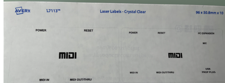
Have been trying to figure out how to relabel the rear panel connectors nicely with my mods and the other metal work to do. Thinking I may laser print on some transparent stickers and I just picked up some of those blank Avery labels from a nearby Officeworks to try out. Need to remove old labels first otherwise they'll still be visible below the clear sticker so tried a cotton Q-tip soaked with Isopropanol and found it could remove a lot of the text initially then seemed to stop doing any more work and still leaving a faint remaining text so I will need to try something else. Acetone is an option once I get some more, but would need to test out on some hidden metal first. This surface seems to be painted and/or lacquered - it's not bare metal and I'm not entirely sure what Acetone will do to it. You can see the real bare metal colour underneath the surface where the lip of the top lid scratches into the back panel a bit.
Before treatment of top left label:
After:
Agonizing a bit over where to put the MIDI DIN-5s. There are the old tuner holes cut out under some new switches I put in which could suit the DIN-5s if I enlarge them and mount vertically, but I found these spots are also rather useful for holding well aligned push button switches and/or that other lockable 4-pin circular connector that is placed there which might be useful for a microphone one day perhaps. I already have the DIN-5 connectors suitable for panels and a smaller mini-DIN6 one too shown below. Was thinking the mini-DIN6 might make a handy custom PropPlug wiring connector if I don't want a USB PropPlug installed permanently (as I potentially already have Wifi on P62/P63) or I could connect it for future external i2c/other expansion use from P14/P15. It's only two I/O pins but sometimes can be useful to expose some I/O for triggering/probing/scoping etc during tests.
There is a nice space already above the video outputs that could suit the DIN5's or anything else I may want sometime. I'd just need to drill it first and really don't want to mess it up or bend the panel while drilling it. Step drilling will be needed as I only have a 1/2" drill chuck and no enlarged single drills over 12mm diameter. The externally mounted connectors should cover the holes at least if they are rough, the key for a good result will be to keep it very well aligned in a straight row when punching the holes to be drilled initially.
Need to commit to a decision soon...already taking longer that I want.
Tried a quick test. Clear stickers seem a decent match when printed in 7 point Arial bold. Will cut out cleanly later or probably just do in one full sticker when it's all properly aligned together and avoiding fingerprints etc.
My agony is over and I ultimately decided to mount my MIDI ports in the bottom left corner where the holes are already nicely aligned but mainly needed expanding to 16mm. I found that the case is stronger there when you press in their connector cables as well and the other connectors I might want down the track are just simple/smaller independent hole cutouts which I can probably put wherever I need to with less alignment needed to look decent. Managed to drill out the MIDI ports cleanly enough for my liking as the rough edge created from the step drill is nicely hidden by the DIN-5 surrounds. Also worked the old labels with more Acetone and it improved further. There are some faint labels still showing on some angles but it's better than before. Happy enough with the result for now and I'll sort out the final label soon. I also obtained something that should hopefully cover the old front panel Topfield PVR label with a custom badge. Need to experiment with that first.
Want to get back to the P2 side of things as well. I've already begun a SPIN2 API for the front panel which can get/set the clock time and date and wake up alarm and poll for button/IR codes. That was mostly working when I left it. The Bull Ant board itself is all checked out except for Wifi and hooking MIDI to a real keyboard for testing the opto-coupler quality.
Tested the MIDI stuff properly after soldering up the connectors and making a long cable to reach my keyboard. I found I needed the 10k base resistor in the end according to this schematic for the opto-coupler. I left it out in the first PCB reflow (DNP) until I could experiment and tune its value because the data sheet is not too forthcoming about how to use it and various people online were saying it's needed to get higher performance. Without it I was getting corrupted serial data, but now I see correct Note On and Note Off messages when I press and release the keys. I also tested the reverse MIDI-OUT transmit path to the synth and I could get it to play sounds too.
Getting a little bit crowded back there but it thankfully all fits. I also ran a USB cable through a grommet temporarily so I can close the case and still use the PropPlug without straining it too much with USB cable movement.
Wow you've gone even further since i last checked this thread. Labels look great, and midi is a big bonus.
The TF7000 I spotted on ebay for au$28 arrived during the week, so hoping to play along with the bullant board you left with us. I haven't checked the power rail ripples just yet, but it does display the 'standby' icon on the VFD, as well as a round dot when any IR command is received, but it never leaves standby. Still, that's perhaps enough to be useful with the bullant
Yeah that is a good sign. Without a booting motherboard feeding data to the VFD module to update the screen it will just sit there by itself and show a standby power indicator icon and flash the dot when it detects IR signal. So you probably have a working screen at least. Old caps were easy to change to fix the supply in case yours does the same as mine - it's a fairly simple switch mode design.
I have your parts and can bring them over soon with the stencil so you can make your board.
Last night I also ran @Wuerfel_21's OPN2 demo with SPDIF via coax and heard some music. I knew it should work if I had output video from the pin before but this was the first time with real digital audio. Will try the TOSLINK output too from an old SID driver patch I made once I move it close enough to reach the optical cable on my amp. I know the LED already works so it should be okay but just need to verify high speed operation at 3.3V. I've put a 5V PCB via right next to it's Vcc pin in case we need mod the optical expansion board power to be run from 5V instead but I don't expect that change would be required. The plan is to also try out an ESP8266 today, just with some stock firmware to see if that path works too.
The SPDIF demo should do TOSLINK as well, just need to change the pin mode to be normal instead of BITDAC
Ok thanks, good idea. I will try that. For some weird reason I somehow thought optical TOSLINK was sent in a different modulated format to coaxial but as they are both biphase mark encoded it should be just a signalling voltage change.
Got it working after some efforts - first had to find an optical cable and figure out how to setup my AVR inputs correctly via it's ancient menu system but it's now working via optical. Just had to flip these two lines in your OPN SPDIF demo code and set the correct output pin number. Then it "just worked", lol.
               wrpin ##P_DAC_75R_2V|P_BITDAC|($F0<<8)|P_ASYNC_TX|P_OE,#spdif_pin
               'wrpin ##P_ASYNC_TX|P_OE|P_INVERT_OUTPUT,#spdif_pin'
Digital audio being detected on front panel.
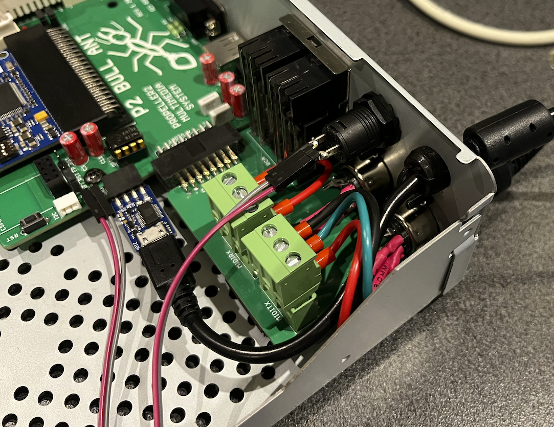
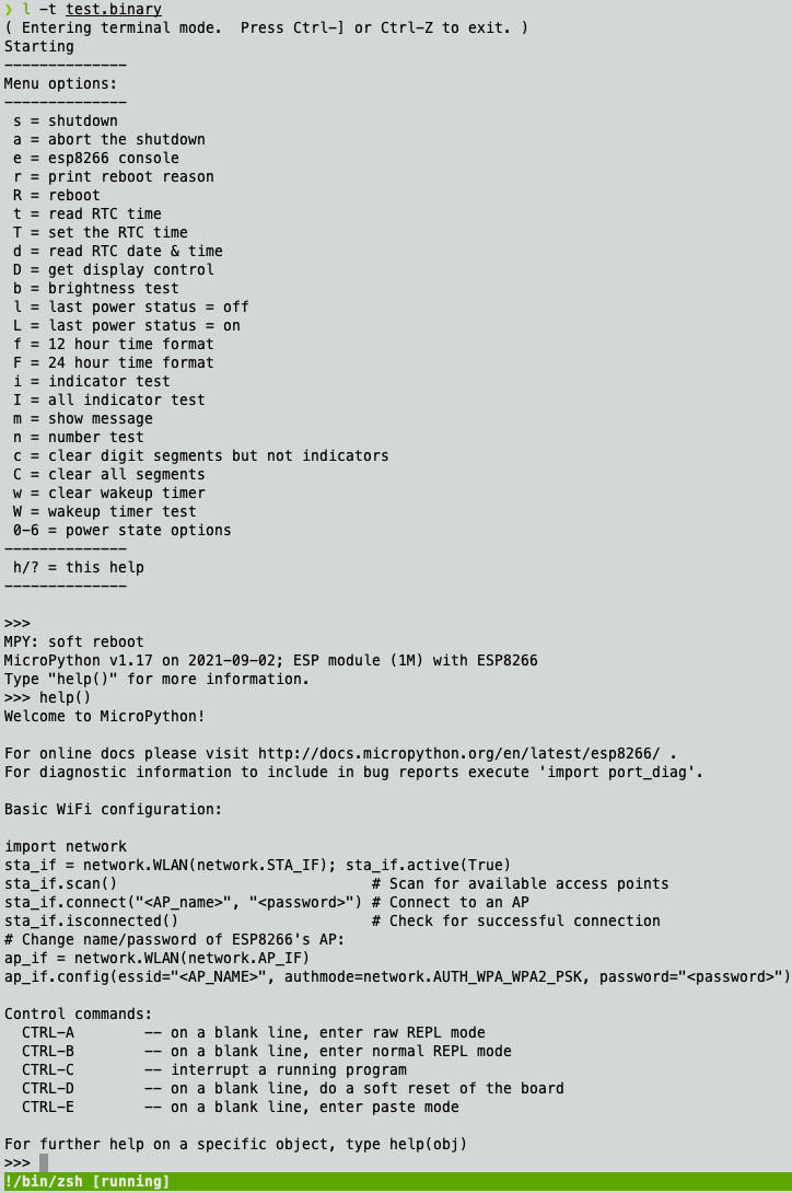
Did a quick test of the serial comms between the ESP8266 and the P2Edge on this Bull Ant project which was the last data path left to be tested to prove all desired features work. Seems to be working. I just used P14/P15 as the serial interface to be replicated on P62/P63 for a "console" and ran whatever firmware I had left lying about on one of my ESP8266 modules that I plugged in. Turns out it was MicroPython of all things LOL. So now I have a built in MicroPython environment if I want to code something for Wifi. Handy.
I get boards from PCBWay and have found that the time saved using the stencil for application and to eliminate tombstoning is worth the $10. For work I have created a bunch of P2 Accessory style boards that are the "standard" circuits we use in our laser tag products, and circuits we want to incorporate later. I will be assembling more this week.
@rogloh This looks like a neat project. I am particularly interested in your WiFi bridge using the ESP-01. I built an accessory board (see image) so that I can do that, but I haven't started yet -- it's about time I graduate from RS-485 to WiFi and Ethernet connections.")
Thanks. Yeah so far it's been working out fairly well. I made it so that the P2 could use either P62/P63 or P14/P15 and the ESP-01 could optionally reboot/wake the P2 in my own setup. The schematic for this block looks a bit messy/complicated as I tried to fit it into a limited space quickly as it evolved without optimally rearranging things and I also multi-purposed some pins but it's quite a simple circuit if redrawn cleanly. I probably should have used more real jumpers instead of solder jumpers so it could be changed dynamically if needed but I doubt I will really need to change it too often once it's all setup in place. The way I designed it is such that the Wifi board can stay powered while the P2 is shutdown and it could wake the P2 when GPIO0 is driven low (RC+diode filtered to avoid issues when ESP boots when it oscillates that pin). The "level shifting style" N channel FETs on the Tx/Rx paths are intended to isolate the P2 from any IO backpowering when the P2 is powered off. The ESP could also instead reset the P2 if required via GPIO2. Also the P2 could optionally reset the ESP (or even reprogram it if required). It's nice to have various options there as some applications would probably like to keep P62/P63 free for debug/download serially with a PropPlug (eg. during development) and some could put the Wifi onto P62/P63 for full remote control etc.
Tested out the SD card extension cable I obtained for this project and it appears to work. I only did a quick rudimentary test with micropython so far reading the root directory of a card but it's a start. I doubt really high read speeds will be obtainable but that's okay - there's already that inline safety resistor on the P2 Edge anyway.
( Entering terminal mode.  Press Ctrl-] or Ctrl-Z to exit. )
#########################
# Native P2 MicroPython #
#   Heap Size: 128 kB   #
#########################
MicroPython v1.13 on 2020-10-13; P2 BOARD with Propeller2 P2X8C4M64P
Type "help()" for more information.
import pyb
import os
sd=pyb.SDCard()
sd.power(1)
True
os.mount(sd,"/sd")
os.chdir("sd")
os.listdir()
['overlays', 'bcm2708-rpi-b-plus.dtb', 'COPYING.linux', 'LICENCE.broadcom', 'issue.txt', '.Trashes', 'bcm2708-rpi-b-rev1.dtb', 'bcm2708-rpi-b.dtb', 'bcm2708-rpi-cm.dtb', 'bcm2708-rpi-zero-w.dtb', 'bcm2708-rpi-zero.dtb', 'bcm2709-rpi-2-b.dtb', 'bcm2710-rpi-2-b.dtb', 'bcm2710-rpi-3-b-plus.dtb', 'bcm2710-rpi-3-b.dtb', 'bcm2710-rpi-cm3.dtb', 'bcm2710-rpi-zero-2-w.dtb', 'bcm2710-rpi-zero-2.dtb', 'bcm2711-rpi-4-b.dtb', 'bcm2711-rpi-400.dtb', 'bcm2711-rpi-cm4.dtb', 'bcm2711-rpi-cm4s.dtb', 'bootcode.bin', 'cmdline.txt', 'config.txt', 'fixup.dat', 'fixup4.dat', 'fixup4cd.dat', 'fixup4db.dat', 'fixup4x.dat', 'fixup_cd.dat', 'fixup_db.dat', 'fixup_x.dat', 'kernel.img', 'kernel7.img', 'kernel7l.img', 'kernel8.img', 'start.elf', 'start4.elf', 'start4cd.elf', 'start4db.elf', 'start4x.elf', 'start_cd.elf', 'start_db.elf', 'start_x.elf', '._.Trashes', '_BOOT_P2.BIX', '.Spotlight-V100', 'testwav.wav', 'PCDOS3_A.IMG', 'PCDOS3_B.IMG', 'System Volume Information']
Am thinking I could potentially cut a thin slot with my Dremel under the front panel at the side to feed the flat flex cable into the inside of the case and then stick the card reader onto the side. Other mounting options are also under consideration. I don't want to mess up the panel.