

Fast HUB75 display driver, display write routines, and other goodies.
 Ding-Batty
Posts: 305
Ding-Batty
Posts: 305
Here, something I have been playing with for a while now, and I think it's ready for the light of day.
I saw Parallax offering 64x64 RGB LED displays, and then saw the P2 LED Cube project, I thought "that looks like fun!", and I thought it would be a good excuse to start working with the P2. So I got a few displays, and the P2 Eval HUB75 Adapter Board.
Then I though, why not get it working with the P1 as a warm-up, so that I fully understand what it takes. I saw Ray's thread on the work done (> ten years ago!) but I wanted to write my own code, and address a few things I thought would work better. One long deep dive later, and here I am, with four versions of the PASM display refresh driver, PASM write helpers, and a pile of test programs. (And I still have not started working with the P2, sigh.)
Two versions of the display driver are bit-banged, and two use the video generator; the fastest one, which therefore allows the most bits per color, sends data at sysclock/4 for each row.
Here are the refresh rates for 64x64 and 64x128 displays at all the numbers of color bits:
Display: 64x64

  Color
  Depth   Waitcnt   Repeat    Vid8clk    Vid4clk
  -----   ------    ------    -------    -------
    1     2888.1    2942.5    4340.3     7800.3
    2      963.9     988.1    1446.8     2601.5
    3      413.2     425.6     620.0     1115.3
    4      192.9     199.2     289.4      520.6
    5       93.3      96.6     140.0      252.0
    6       45.9      47.6      68.9      124.0
    7       22.8      23.6      34.2       61.5
    8       11.3      11.8      17.0       30.6

Display: 128x64 (two 64x64 panels in series)

  COLOR_DEPTH=8 is not available because the display buffer would take up _all_
  of hub ram: 32KiB -- it also would flicker too much, anyway.

  Color
  Depth   Waitcnt   Repeat    Vid8clk    Vid4clk
  -----   ------    ------    -------    -------
    1     1530.3    1545.5    2297.8     4336.5
    2      510.5     517.2     765.9     1445.9
    3      218.8     222.2     328.3      619.8
    4      102.1     103.9     153.2      289.3
    5       49.4      50.3      74.1      140.0
    6       24.3      24.8      36.5       68.9
    7       12.1      12.3      18.1       34.2
    8       n/a       n/a       n/a        n/a
Note that any refresh rate < 60Hz will probably have too much flicker.
The display uses one byte for each pair of LEDs on the display, so a 64x64 display uses 2KiB for each bit of color.
Along with that, there is a PASM write helper to write to the display buffer, since the memory layout of the pixels is designed for display refresh speed, and is otherwise... inconvenient.
There are six test programs included, each of which exploring something specific. I was looking mostly at digit displays (think clocks or counters), and exploring digit change animations, so there is heavy focus on that in those test programs. The most recent, and probably most elaborate and complete, is test_clock_bitmap.spin which implements a digital clock, 4 or 6 digits, 12/24 hour, with control over time, color, intensity, and many digit change animations. (The digits are ROM font bitmaps.)
In addition, because using a higher numbers of color bits and larger displays, the display buffer can get quite large, I did some, ah, unusual things to maximize the available hub memory for the display buffer, including reusing not only all the PASM cog images in hub memory, but also other init-specific Spin code; the clock example recovers about 4KiB that way. This is discussed in the file large_buffers.txt.
I also have, if folks are interested, the set of about 14 test programs I wrote to get a handle on synchronizing the Waitvid data hand-off point, hub access, and a separate clock, based on video work @kuroneko did many years ago.
Right now I only have displays based on the ICN2037 controller chip, so that is all I have tested. I know that the P2 HUB75 driver that @"Stephen Moraco" has shepherded can handle many more.
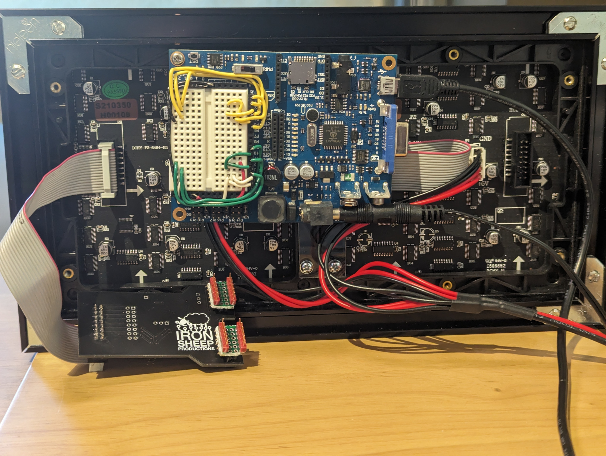
Here are a few photos of my set-up -- using a Board of Education to use the prototyping area -- and the P2 Hub Adapter Board, with breadboard pin adapters:


Comments
Yes, I was also curries about that too, I was only able to drive one to two panels with the P1.
Mike
The display buffer requires 2KiB per 64x64 panel per bit of color depth. It should be able to drive 3 or 4 panels, up to three bits of color depth (with limited code space left over using 4 panels + 3 color bits == 24KiB for the display buffer), and still get about 300 refreshes per second (i.e. no flicker).
Note that I have not yet tested that -- I have ordered more panels in various sizes for further testing.
(I think that is what you were curious about, but you weren't clear.)
The next round of changes mostly involves small improvements to the number of color bits (now allows up to 10 bits per color, depending on space); some very small speed-ups, with more accurate refresh timings; some changes to the "split" FDS object to allow use during the discarded init code.
But I have also added a new test program, that I call "gamma_explorer". It shows two intensity gradients on the display: the top half is the simple "linear" intensity, while the bottom half shows the gradient adjusted with gamma correction.
Because our eyes are more sensitive to dim intensity changes than to bright, the linear gradient will look like it gets too bright too fast. The gamma-adjusted one will look better, for the "right" gamma value. But to get a good gamma adjustment, more display bits are needed than for the desired number of intensities -- typical rule-of-thumb is that for a good gamma-adjusted display of three bits per color, you need a 6 bits per color display. For a gamma value of 2.2, and three bit color depth, the gradient looks pretty good (as seen in the attached picture of a 128x64 display).
The gamma_explorer allows adjusting the gamma from 1.0 to 5.0, with 2.0 to 2.6 as the most reasonable range; the number of color bits can be adjusted from 2 to 10 (reduced/extended to the actual display color depth); the color can be changed (red, green, blue, white); and the gamma mapping table can be dumped in a form that could be used in another program.
The gamma calculation, done on the P1 using the log and antilog tables, was a fun project, trying to minimize the differences between the P1 calculation and the equivalent calculation done in double-precision floating point on a PC.
This is a full update of most or all of the files in the original zip file -- it's probably time to submit it, in whole or in parts, to the OBEX.
I finally got around to uploading the latest version (included in my previous comment) to the ObEx: https://obex.parallax.com/obex/hub75-display-drivers-and-demos/