

Analogue daughter board ID
 ManAtWork
Posts: 2,369
ManAtWork
Posts: 2,369
I have a main board with a P2 on which I can plug a daughter board with several analogue and digital IO functions on it. I plan to make diffenet versions of the daughter board in the future. They will be pin-for-pin compatible but have different characteristics such as different output power and gain or sensitivity. The daughter board has no memory and there are no spare pins left over. I'd like to be able to distinguish at least 4 different versions.
Of course, I can store the version of the daughter board somewhere in a file or protected flash memory region of the main board so that it can still look up the daughter board version even after a software update. However, I know Murphy's Law and I'm almost sure that somebody will mess things up by plugging the wrong daugther board in. This won't damage the board itself because it's self protecting but it may burn other devices connected to it because, for example, gain and current limit parameters are not set correctly.
I think, this is a perfect application of the smart pins of the P2. At the moment I have two ideas:
1. I can add a small capacitor to a non-time-critical input of the daughter board. For example, there is an enable/reset input. 1 means enable and 0 means reset. It has a pull-down resistor so it defaults to reset. If I add a 1nF capacitor to ground I can enable it and then let the pin float and measure the RC decay time it takes to fall back to the reset state. Alternate versions could use 0, 2.2 and 4.7nF.
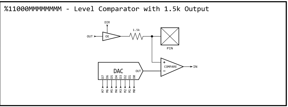
2. I can add a voltage divider to an output of the daughter board. For example, there is a status pin, 0 means fault and 1 means OK. With a voltage divider I can reduce the voltage level of a logical "1" from 3.3 to say 3.0V. Of course, it still has to be well above the 1.65V threshold with some headroom for tolerances and noise, but 3.3V, 3.0V, 2.7V and 2.4V should be well distinguishable. I can use the DAC comperator mode and a two step aproximation. (ADC would require calibration and is too much trouble).
3. I could combine both options to distinguish even more differnt versions.
Any other ideas? Measuring the current draw of an external pull-up or pull-down resitor to determine its value is not that easy, I think. Is it possible to use the 1mA output and the DAC comperator input mode at the same time?
Comments
Yes (to the other ideas), but may not be trivial to add.
The recognition of the auxiliary board is one thing but making the setup completely fool proof is another, most difficult and expensive.
Are these extra elements prone to be damaged on the main board or completely off both boards ?
Have you considered using different auxiliary board mask colors to visually indicate to the user they got something wrong in their hands ?
As you might have already guessed, I'm talking about the VFD board of my CNC controller. The end user is not the problem. He should be locked out here, anyway. 230V is dangerous. If the end user touches anything inside the box I disclaim any responsibility. But even qualified service personnel can make mistakes and I don't exclude myself.
Too expensive. I plan to use the same PCB layout, at least for the first two versions. I even will use the exact same IGBTs for different current ratings because it's more expensive to stock two different parts. Only the size of the heatsink and the sensitivity of the current sensors will be different.
It's the spindle motor. The only really critical parameter is the current limit. If there's a high power board installed while the controller thinks it's a low power board it will drive twice the current trough the motor which burns it very quickly. If any other parameter is wrong the motor will simply stall. That maybe ruins the cutter bit but the user will immediately notice it and stop the machine hopefully before it gets too expensive.
I know and I don't even try that. That would mean competing with all suppliers with off-the-shelf VFDs which have nice front panels with small keyboards and manuals with hundreds of pages explaining how to setup any imaginable motor model. This also means support calls and so on and a million ways to do it wrong. No, the only thing the end user can do is to select one motor model out of a predefined list of approved spindles.
So all I want to do is to check if the right board is installed. If not I throw an "Internal configuration error" and shutdown everything. The end user can't fix this anyway.
Think chip posted example for octal invaders game where used one pin for 6 or maybe it was 8 resistance levels for user input
Hmmm, I think this mode should do it.
I have three pullup resistors in front of my isolation couplers for the PWM signals.
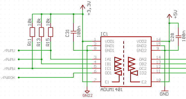
It doesn't matter if they are 10k or 4.7k. The leakage current is less than 1mA for both values when I actively drive the signals and they only provide a defined state when the P2 pins are tri-stated. With the comparator mode above it should be possible to detect which of 4.7k or 10k is connected. So 8 different versions can be encoded.
BTW, the ADUM isolation coupler is obsolete, but I still have an almost full reel left over from my past servo driver experiments. The same is true for the hall effect current sensors (Allegro ACS710-6 and -12). I have plenty of them but they are no longer produced. This means I have to route another layout after the first ~300 units produced. But good for the environment and my wallet...")
CA-IS3720/21/22 are the replacement types, smaller, faster and available.
Why would you say ADUM1401 are discontinued ? Digi Key has lots of them in stock (horribly expensive, yes) but most of them are shown as being in "Active" status and only some parts are discontinued. Mouser has tons of them available as well but also at a premium.
edit - my bad, you said obsolete and that is correct") .
.