

Official P2 clock max. recommended frequency?
 Rayman
Posts: 16,460
Rayman
Posts: 16,460
I looked everywhere, but can't find anything in the Parallax docs saying what the max. recommended frequency for the P2 is. Anybody see it somewhere?
Think I remember Chip saying 160 MHz at one time. Think maybe 180 MHz is default for FlexProp (?).
I see some Parallax examples that require 250 MHz (as I recall).
Anyway, it would be nice to know what is 100% safe for indoor, non-automotive use.
From what I've seen, even my P2 boards are error free at 300 MHz, but not sure I'd go that far in an actual application. Maybe 250? Don't really need speed in main application, upgrading from P1. Just want to make sure I'm in Parallax endorsed territory..
Comments
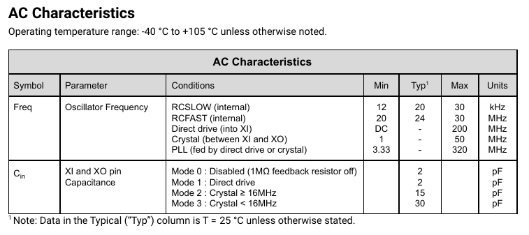
Amazingly, Parallax has opted to specific 320 MHz in the datasheet! It probably needs to include a caveat on wattage and cooling.
The target spec used during OnSemi's place and route was 180MHz initially, I'm not sure what their final reported corner case was ?
That was for Min Vcc and corner process and Max temperature (125'C die ).
Maybe they mean the VCO range there ? or maybe the 320MHz belongs in the typical column ?
They can't really spec P2 core to guarantee 320MHz at 105'C and min Vcc and all process variations.
I tortured my P2s at 354 MHz for a long time. What I did at this frequency and a room temperature (22-28C, about 70-80F) worked stable, without glitches.") ... or from 200 * Atari 800 to 190 * Atari 800)
... or from 200 * Atari 800 to 190 * Atari 800)
However, when I started to use PSRAMs, 354 MHz was not stable enough. There were glitches from time to time, including crashed cogs.
So I lowered my "standard" frequency from 354 to 336 MHz (from 100 * Paula to 95 * Paula
I use this 336 MHz for all things I do with P2s, except robots, where the frequency is set to what the HDMI LCD display needs and it is 285 MHz.
I didn't notice any problems at 336 MHz using several P2s (we bought 40 (non-PSRAM) Edges for robots; I didn't test them all, but at least 10 of them were tortured at 354 and 336 MHz before they ended in a robot's brain at 285 MHz )
Also I didn't notice any bad things using NeoYume and MegaYume, which also works at somethng like 340 MHz, except the "yolkless" cog on a P2-EC32, but this cog fails there even at much lower speed (while the other cogs work).
I experimented with a P2-EC32 and PSRAM driver to determine where is the safe boundary for a clock frequency. I found first glitches somewhere over 340 MHz. While the program didn't crash, the audio driver started to generate clicks. This of course may be only a PSRAM, that's heavily overclocked, and not a P2.
The conclusion: for non-critical everyday use, players, games, emulators, 340 MHz is ok. The P2, in either EC-32 or Eval, is stable there while in a room temperature.
For more critical things, the rule is always the same: use the lowest possible frequency that is enough. For stuff using HDMI, this is of course 250 MHz.
The die temp will be a lot higher with heavy processing. Fast Streamer activity is known to have the biggest impact on power demand so therefore something like external RAM transfers will generate notably extra heat. This in turn lowers the max frequency of reliable hubRAM operation as per https://forums.parallax.com/discussion/comment/1545243/#Comment_1545243
The player is demanding. The audio player cog uses interrupts at 3.54 MHz. The video driver cog outputs HDMI at 33.6 MHz pixel clock, using PSRAM based framebuffer and then then adding sprites from HUB RAM on the fly. The PSRAM driver has to service the video and, if playing Amiga modules, also the audio: sample buffers are placed in PSRAM; the animated sample info panel also needs PSRAM transfer. The oscilloscope is drawn 50 times per second. While playing SIDs, there is 6502 emulator cog and the SIDCog working at 495 kHz. The SIDCog is modified to enable placing its channels independently in the stereo base, so every channel has now its own filter. Near 100% of cog power is used at 336 MHz to do this. The P2 is hot. Still stable on my desk, but I don't know if it can be stable when put in a tight, plastic case.
I also think that the specifications in the "AC characteristics" of the data sheet are meant for the oscillator circuit only, and doesn't guarantee reliable code execution at all frequencies and over the full temperature and supply voltage range.
I think 180MHz should be pretty safe as it leaves a safety factor of two for process and supply variations if the temperature doesn't rise above 80° according to this graph. I use 200MHz as clock frequency for my industrial controller projects as it is an even multiple of the 50MHz I need for the Etrhernet PHY and it still should be rather safe.
Using external memory not only depends on the reliable code execution (cog and hubram access) but also on the timing of the IO pins which is much more sensible to routing delay, line termination (ringing, reflected waves), metastability, EMI and other effects. Possible glitches that cause bad pixels or clicks in the audio do not much harm but I'd consider code execution from external memory combined with overclocking somewhat risky. As the propeller doesn't have any watchdog, MMU or other protection a crashing P2 could wildly toggle any output pins and trigger all kinds of nasty events.
Anecdotal Evidence at 270Mhz.
I have had 5 P2s, outside in small unventilated enclosures with power supplies running at 270Mhz will all 8 cogs enabled since early November. These were running my Christmas light show. Temperatures in that time were from 82F to -1F. Zero operational problems. The past two years I have had to reboot the commercially purchased ARM based controllers about once every 2 weeks. They would simply "lock-up". No reboots with the P2 based controllers, and the temperature extremes were much wider than the previous two years.
When I started adding audio to NeoYume, booting the additional cogs apparently shifted the IO timing just enough to where it would crash after a few minutes due to memory glitches (though insulated from actually crashing the P2 with nasty side-effects by the 68000 emulation). Looked a bit like this:

Relatedly, it really is room-temperature-only (without active cooling ig). This is what happens when you heat up a P2EDGE with a hairdryer:

(The audio going silent is actually weird, since the audio subsystem only uses PSRAM to load sample data. Either the glitchy 68000 code managed to send a command sequence to that extent through the mailbox system or the YM2610 cog itself somehow locked up)
FWIW I have run several P2’s in hot industrial settings (refinery) at 320 mhz without issues. We are talking >130F ambient, zero draft, NEMA explosion-proof housing. On one I pre-emptively stuck a little heatsink on the chip out of some sense of compassion, but it really didnt seem to care either way. Never had a hitch.
Anecdotally also, Rev D Edge modules had an extra slug of copper layer added and will perform more consistently at higher temps / high speed.
Really mentioning in-case anyone is thinking of putting time into running tests on Edge modules... it would be well worth starting with RevD's.
At extreme overclocking levels, P2-Eval's should perform best I'd have thought (given the significantly larger copper heat spreader), or customer made boards that prioritise thermal and power over size.
It's just kind of strange that recommended/max clock speed is one of the first thing mentioned for other MCUs.
But for P2, no mention of it hardly anywhere...
I guess what @evanh found is the closest we have, 320 MHz.
My own 2-layer boards die above 310 MHz. But, is that the chip's fault or my board design?
You can expect the best performance if you have a solid ground plane that can transfer as much heat as possible away from the center pad. Two-layer boards have the problem that you normally need the top layer for the IO signals and the bottom layer for the ground plane. So you have none left for anything else. You can place the 1.8V supply ring between the center pad and the IO pads but you also need a second ring for the 3.3V supply. Then you have to either "sew" between the IO signals and the ground plane with lots of vias or you cut the ground plane and place the 3.3V ring on the bottom layer. This makes the heatsink plane an island limiting its ability to spread the heat. You can compensate this by adding an aluminium heatsink on top of the P2 but the cost also compensates the advantage of the two layer PCB.
So I'd recommend always using 4 layers except for very simple designs that require only a few IOs or run at <200MHz so they don't get hot.
Recommended max for the RP2040 is 133MHz but...
Not even warm to the touch