

FTDI EVE Audio --> P2 Input --> P2 Output with A/V Accessory
 Rayman
Posts: 16,460
Rayman
Posts: 16,460
Adding audio support for an FTDI EVE2 display driver.
The EVE2 audio is basically a 141 kHz square wave with the high time modulated to give audio when filtered a lot.
I have a circuit where I implemented FTDI's filter circuit and connected that to MAX4411 amp.
That works pretty well.
But now, looking to capture the digital audio stream and send to DAC output using the Parallax A/V Accessory.
Pretty much have it working, but there's something strange at the low frequency end.
I've attached the .spin2 driver that does the above.
Not sure why had to add debouncing with waitx #100.
The output sounds pretty good into amplified speaker.
But, with headphones, there is a hiss without the digital low pass filter in the code.
Also, a bell at 164.81Hz is basically inaudible with headphones, but sounds fine with amplified speakers.
Not really sure what is going on with this... Any ideas?
Comments
Maybe the 990 Ohm DAC is too high impedance? But I think that would affect the high frequencies first.
The TPA4411 on the AV board was replaced with direct DAC output on the HD audio board. There must be a good reason for that. On paper the TPA4411 looks like it would be great since it generates a split supply and does not need output DC blocking capacitors.
Maybe it's the headphones? A lot of them seem to have a bowl-shaped frequency response.
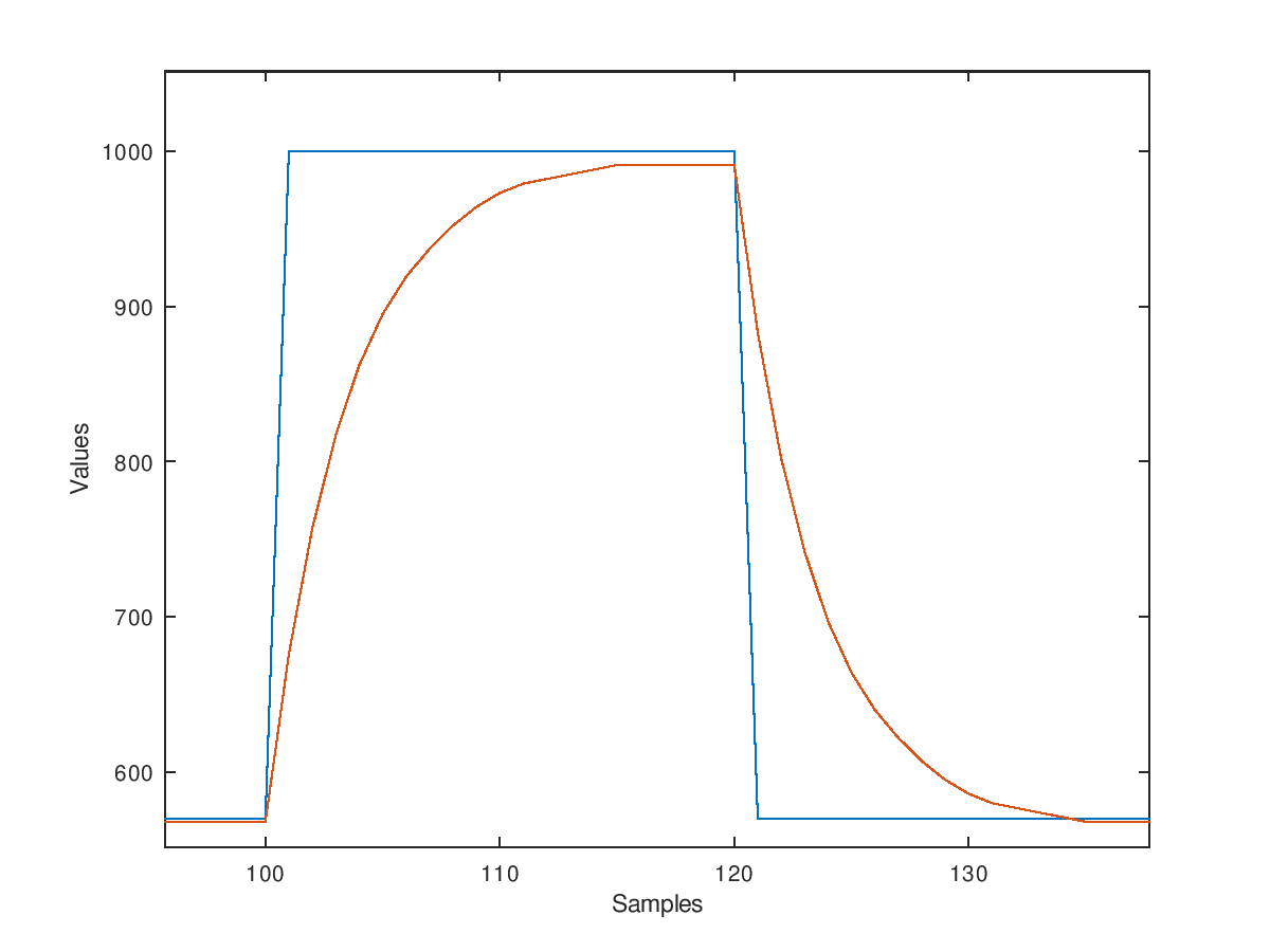
The filter looks decent in the time domain.
The EVE could be doing some pre-emphasis or delta sigma noise shaping to compensate for the RC lowpass filter that it expects.
Polling the pulse width in PASM like this may be introducing some LSB jitter if the measured time is varying slightly between measured samples for the same actual width due to when the edges are seen relative to the code executing. You may be able to look for a smartpin mode that measures the width more consistently.
As to your headphone issue, that seems more like a frequency response problem.
Your debouncing may be an indication of glitches. You could scope the signal and check if there are any narrow pulses outside the expected PWM range with a suitable digital scope's triggering mode.
You could probably bypass the whole filter rigmarole and just feed the digital input straight into a pin. Then set the ADC smart mode while leaving the low-level pin in digital mode. This in theory should give you a decent-ish approximation of the original signal. I guess you'd want to implement the same filter characteristics in software on top of that.
I like this idea.
The EVE2 output may not be pure PWM. It could be pulse density modulation. That is similar to what the P2 ADC generates. That could explain the "glitches." Or, the glitches could be a result of adjusting the duty cycle mid-period. It could also be ringing. A 30-100 Ohm series resistor in the PWM line should fix that.
The appeal of reading the PWM width is that it provides a sample clock as well as the data. The PWM period of the EVE2 won't exactly match the same number of P2 clocks every time. That is a potential noise source. You would want to divide by the measured PWM period to calculate the duty cycle.
@Wuerfel_21 Are you suggesting using the sinc2 or sinc3 ADC filters? It wasn't clear that would work. Might be worth a shot.
@SaucySoliton I didn't realize the A/V board had a TPA4411 instead of MAX4411. Diabolical using the same number...
(or maybe it's best for both companies to have a drop in alternative source?)
I'm thinking the TPA4411 isn't as good at the low frequency end into cheap, unpowered headphones/speakers.
I don't know what impedance the headphones or speakers I tested with are, but if 8 Ohms, would make sense.
It sounds OK with powered headphones and speakers.
Suppose could also implement a pulse width filter that only accepts a certain range of widths.
But, what I have seems to be OK for now, with bell sounds.
Maybe re-evaluate with more complex sounds later on...
It might be the Maxim part. I didn't find an official bom after searching a bit so I just grabbed my AV board and read the chip markings. It says:
The sinc2 filter is usable up to 11585 clocks per sample, I think. The sinc3 filter is usable up to 511 clocks per sample. These values guarantee that the filter output is well behaved even if the input is constant 0s or 1s.
More on the sinc filters: https://forums.parallax.com/discussion/comment/1523646#Comment_1523646
I'm not sure if it would be best to try to sample at an integer fraction of 141khz or not. I think your sysclock is 160Mhz. I would start with a sampling interval of 8192 clocks to get good low pass filtering. That would give a sample rate of 19.53Khz. You'll need to use sinc2 just because 8192 is way larger than the 511 clock limit for sinc3. It might also be worth trying sinc1 (smart pin mode %01111).