

Modular CNC controller
 ManAtWork
Posts: 2,369
ManAtWork
Posts: 2,369
I know, I'm good at starting new projects and not so good at finishing them... ![]() But this time I'm rather optimistic. Actually, I started this project 3 years ago and the original design used P1s for the main module and the axis modules. But the P1 was a bit under-powered, at least for the main module where I soon ran out of memory. So I did a re-design in 2020 using an ARM CPU for the main module. But I had to kick that one out due to poor availability of the hardware and to much frustration in the software development. And during the COVID crisis I haven't got much time for creative work but was busy with redesigning PCB layouts to fit the available components.
But this time I'm rather optimistic. Actually, I started this project 3 years ago and the original design used P1s for the main module and the axis modules. But the P1 was a bit under-powered, at least for the main module where I soon ran out of memory. So I did a re-design in 2020 using an ARM CPU for the main module. But I had to kick that one out due to poor availability of the hardware and to much frustration in the software development. And during the COVID crisis I haven't got much time for creative work but was busy with redesigning PCB layouts to fit the available components.
But now I finally managed to design and build a P2 based main module. 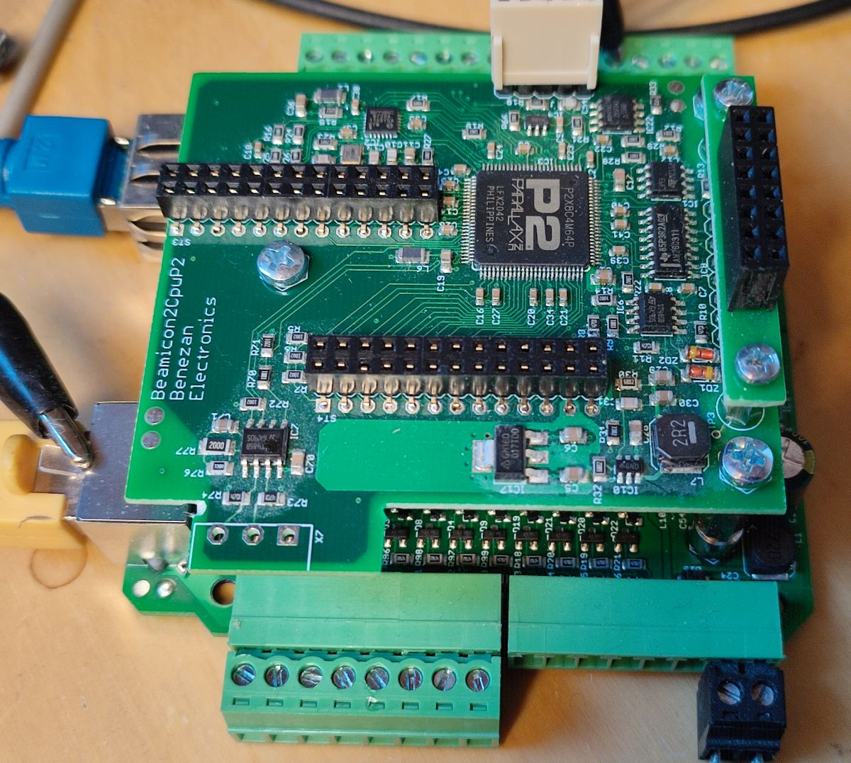
Coding the drivers for all the included interfaces took only a couple of days. So I hope I can soon start with the actual application.
How is it supposed to work? Similar to my previous CNC boards it also won't be a complete stand-alone controller with it's own GUI but instead has to be connected to a PC which acts as user interface, runs the G-code interpreter and does all the higher level calculations for the trajectory planner. The main module with the P2 has an Ethernet interface and receives the trajectory as stream of position vectors and IO commands. It performs the low-level computations such as acceleration/decelleration ramps and position interpolation for the individual axes.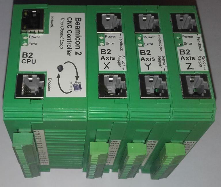
Each of the axis modules contains a P1 and is responsible for the signal generation for that particular axis. This can be one of the following:
1. Step/Dir signals (open loop)
2. +/-10V analogue servo amplifiers with encoder or glass scale feedback (closed loop)
3. MODBUS digital servo controllers
All modules share a common bus which is based on several RS422 (differential) lines. The topology is similar to that of an earlier project and also has a clock, a MOSI and a MISO line. But the clock is used for synchronisation only and not for the actual data transmission which is instead done in "UART mode", e.g. with start and stop bits. 5Mbd data rate allows transmission of 24 bytes per module every millisecond.
The main module can address up to 16 axis (or IO) modules. A daisy-chain enumeration is done during booting so that no DIP switches are required to set the adresses like for common RS485 based protocols. The adresses are instead assigned in the order the modules are stacked together.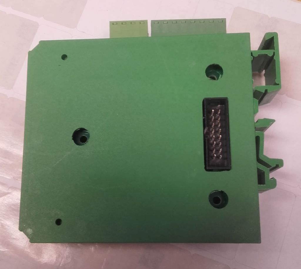
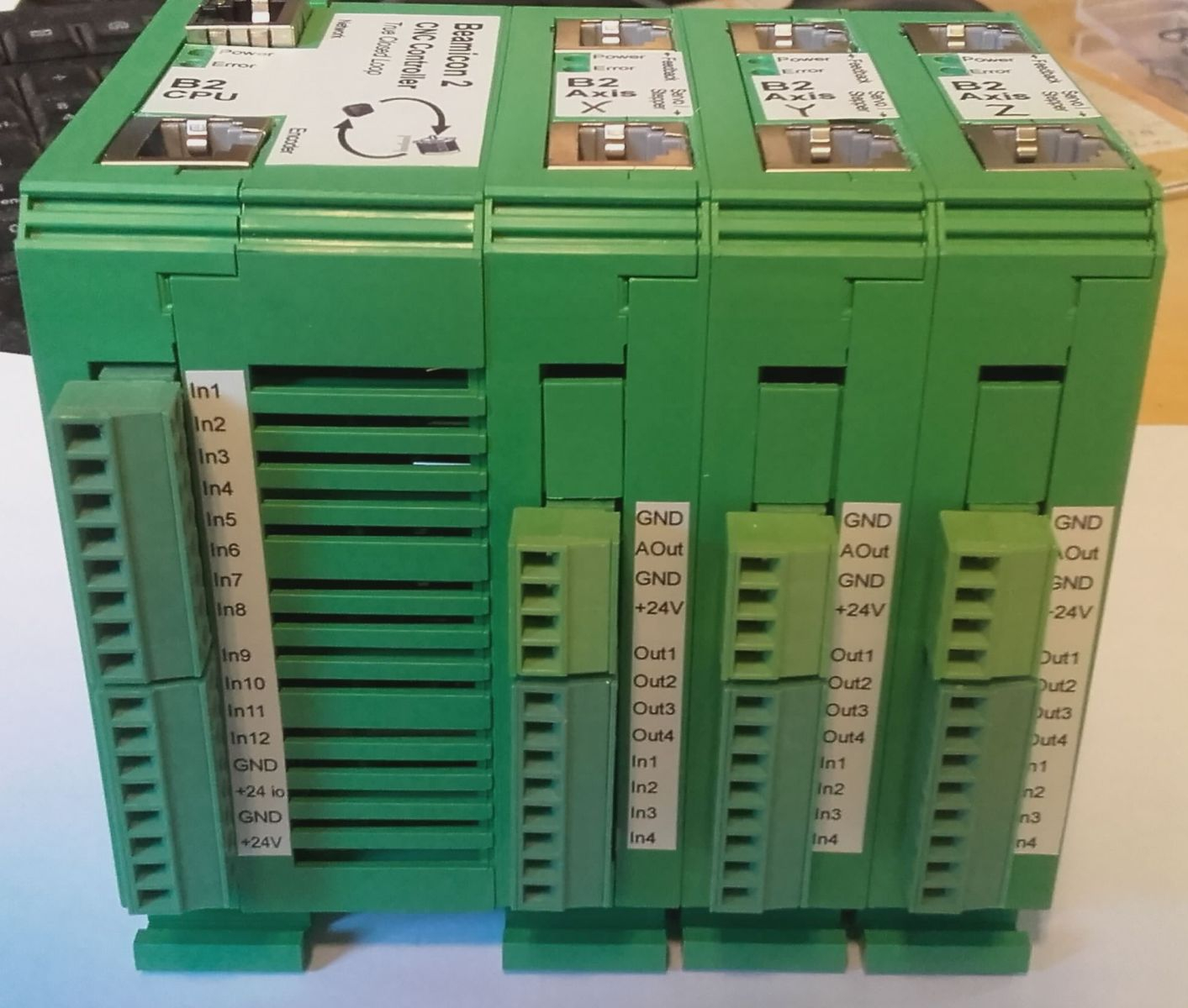
Main module feature list:
- 100Mb Ethernet interface
- Encoder input for main spindle (for synchronous tapping or gear-cutting)
- 12 digital inputs (24V)
- 8 digital outputs (24V 250mA, can drive relays and solenoids directly)
- 2 analogue inputs and 2 outputs 0..10V (isolated)
- 1 PWM output (isolated)
Axis Module feature list:
- Step/Dir command output with additional enable+status signal
- Encoder feedback input (incremental or RS485 based absolute)
- Analogue Sin/Cos 1Vpp glass scale input (up to 10nm resolution)
- +/-10V output for analogue servo amplifiers
- 4 digital inputs and 4 outputs (24V)
Comments
Very cool!
Very nice, thanks for sharing
Cool...we need more industrial products
Craig
@ManAtWork
10nm achievable?
What motor command resolution are you getting and loop rates?
🤔
Sub-micron app-note. PDF too big to upload:
https://dropbox.com/s/78luza62zfopp8p/sub%20micron%20note5527.pdf?dl=0
[sinister chuckle ]
]
10nm is overkill for position control. But say you want 1µm resolution at 1kHz update rate. That means your velocity resolution is 1mm/s. Or at a reasonable feed rate of 600mm/min the quantisation error is +/-10%. So it's always a good idea to have a much higher encoder or glass scale resolution than required for position control alone. That reduces dithering and grunting noises at low speed.
Todays digital servo controllers usually have a current control loop running at the PWM frequency (10 to 20kHz), a velocity loop at 3..5kHz and a position loop update rate of around 1kHz. That doesn't mean that the overall corner frequency is 1kHz. It highly depends on the stiffnes and the mass to elasticity ratio of the mechanics.
BTW, true analogue servos still have competitive performance. My SMT P&P machine has a big audio power stage as servo amplifier with 80V DC supply and big heatsinks. You need state of the art DSP power and encoders with incredible resolution to beat that with a digital system.
We are in 100% agreement
By "true analogue", we talking tach-feedback?
IIRC, some manfacturers (flying shears?) refuse digital completely but this was a few years ago.
I am with a customer right now and just as I was reading your post, he approached me with a first-off workpiece that literally dropped-in to his ~zero tolerance gauge which always amazes him because this is a 1997 piece of equipment that has had very little maintenance attention.
His brush-type motors have tach-feedback and the linear axis (carriage) has a precision rack for the rotary encoder. The encoder gear is spring-loaded into the rack (zero backlash).
IMO, the industry has gone backwards because they are utilising the encoder/resolver on the back-end of the motor for axis position feedback....what about the drive-train backlash! The CNC controller is satisfied that the axis is within tolerance
My preferred aproach is Dual-Loop-Feedback:
Option #1) Motor feedback... D term, Load feedback... P term and I term
Option #2) Motor feedback... P term and D term, Load feedback... I term
It's amazing; machines with not-so-great drivetrains can, within-reason, eliminate backlash completely.
Craig
But you have to consider that there is always some time shift between motor feedback (directly coupled) and load feedback (attached over a spring/mass system). That's no problem if you do non-overlapping point-to-point movements preferably with single axes, only. The you can eliminate backlash completely. As soon as multiple axes move simultanously at non-constant speed, for example small circles, the trajectory gets distorted if the delays are not matched.
It also makes a huge difference if the backlash is past the dominant inertia (usually the ball screw), i.e. in the nut, or before it (at the motor/screw coupling). In the latter case the motor might accelerate violently while getting over the backlash which can cause overshot or oscillations in the drive chain.
Milestone update...
next to-do item on the list:
I have a working version in P1 ASM but that one was coded for least possible memory footprint (16 bit math). I also have an improved version running on an ARM µC or PC but that requires floating point math. The P2 has no FPU but should be fast enough to use emulated floatingpoint operations for all calculations that only has to be computed once per 1ms cycle. But some parts of the ramp generator use digital filters and need a real lot of operations. So I have to re-code those using 32 bit fixed-point and the CORDIC.
Sure but OTOH, a small change in direction can mean that the motor only rotates within the backlash and the tool doesn't actually move.
There is also the 3rd option that I tend to use with hydraulic servos:
Option #3) Motor feedback... PID, Load feedback... Target position
Another benefit of dual-loop is that; in the event of something like a slipping coupling or other gradual loss of position, the window of error between the two feedback devices will trap the issue before one is knee-deep in scrap parts.
Update: the position vector buffer, interpolator and acceleration ramp generator works. The math is implemented using 64 bit fixed point calculations. The innermost loop of the decelleration ramp generator required hand optimized assembler but everything else uses C.
BTW, it's extremely handy that, opposed to the real world, the time axis can be mirrored when simulating classic newtonian mechanics.")
Do you have a minimum move Block Time?
What do you do when the Block Time is shorter than the acceleration would take to get to the feed rate?
How do you handle multiple short Block Time moves strung together?
sin/cos 1vpp encoders need some fast analog to digital converters...
I don't know what you mean with "block time". But the algorithm for the acceleration/deceleration ramp planner is pretty simple. I draw a positive slope from the start point and a negative slope backward from the endpoint. The desired feedrate is the horizontal line. Velocity is on the Y axis. The area under the lines is the distance travelled. The buffer can grow dynamically on the right side while the machine is moving. I just have to redraw the negative slope.
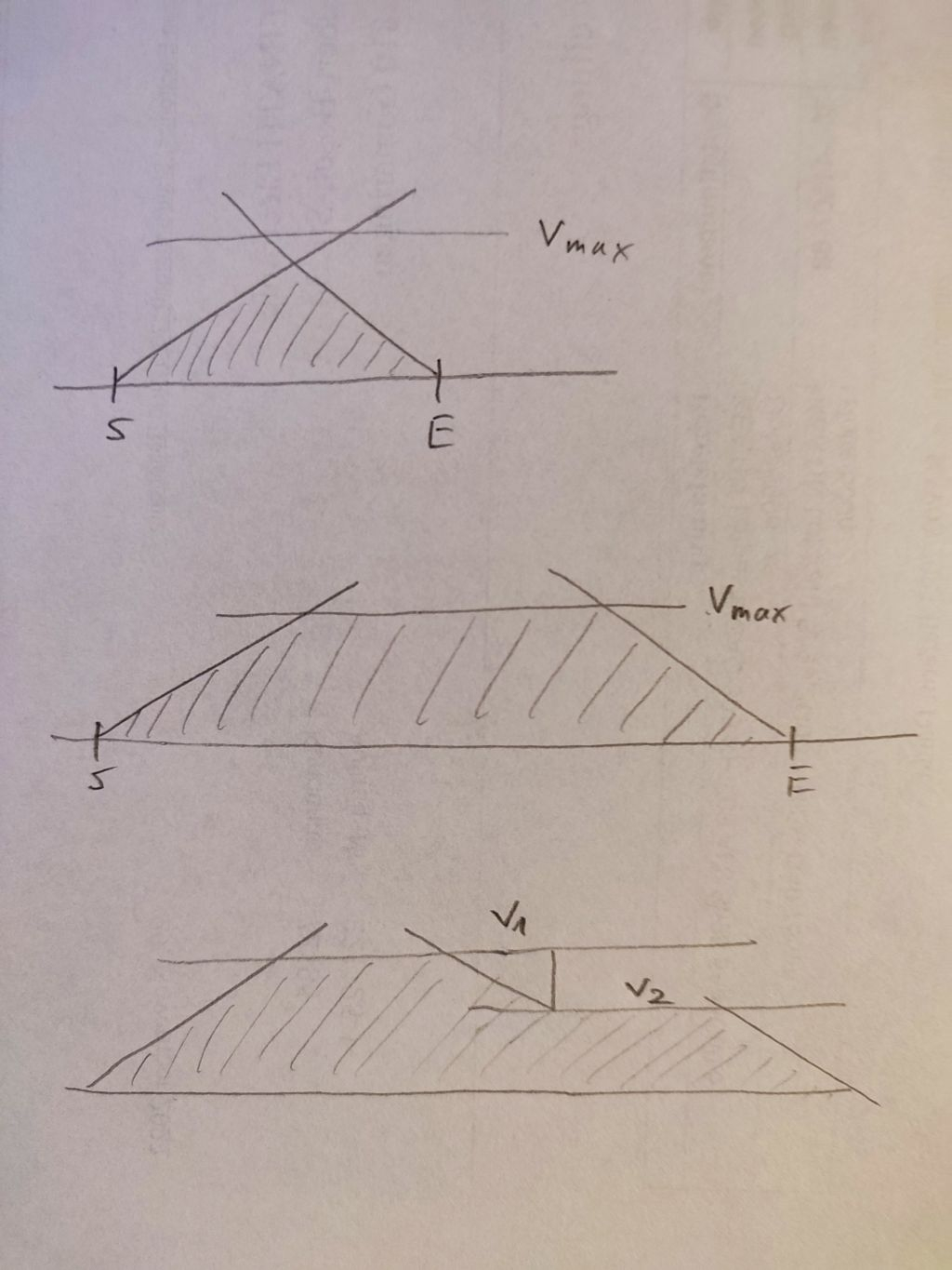
I use external 12 bit ADCs with 250kS/s because the counter based ADCs of the P1 are too noisy and the P2 is too expensive for each axis module.
Da is distance to accel
Dd is distance to decel
Td is total move distance
@ManAtWork
I understand that your axis technology based on the P1 already exists but why not have the modules be simple buffers and handle all the axes on one P2?
1MHz encoder frequency is not exactly trail blazing today, right? 🤔
Block is the way points generated by the programmer or CAM system. They really don't need to be so tight. Machine responses are finite.
I recently learned from a Kuka Robotics engineer that they run at 14ms updates 😲
I run at 2ms.
P2 doesn't even break a sweat 😁
@ManAtWork
Block time is the move time without any acc/dec
The gcode line G1G91X10F600 has a block time of 1 second if feed units are mm/min (600mm/min -> 10mm/sec, so 1 second to go 10mm
The gcode line G1G91X10Y10F600 has a block time of 1.41 seconds.
I'm familiar with the Fanuc acceleration time constant approach to acc/dec
Your acceleration and deceleration rate is for the move vector? (when more than 1 axis moving in coordination)
@Mickster
Yea, I understand your program...
I kind of look at it like the decel part starts before the accel finishes, so during the overlap the velocity stays constant...
And going from this:
... to this:
is putting on your calculus hat, to perform an integration.
PS: That's as far as my education went, but I'm happy to say I have used all my school maths because of such motion control work.
That's mainly a marketing decision. It looks much more professional in proper casing instead of a big blank PCB and therefore I can charge a higher price. The P2 would probably have enough CPU power to handle up to 10 axes and all IOs. But all the connectors would take a lot of space on a single PCB and I might run out of IO pins. And the modular design is much more flexible if I encounter different interface requirements in the future.
An incremental encoder @ 1MHz is plenty for the main spindle. The servo axes can have absolute encoders with a digital data interface so there is no counting frequency limit.
About block time: There is no limit on the G-code side. The controller can process as many lines as the PC can read from a file. 100 or 1000 lines per second is no problem. Not that this is really needed but some users overdo it and output a line every 1/100mm or so. The PC then breaks it down to 200 vector samples per second (5ms time slice), that's what goes into the buffer. To avoid polygon ("disco ball") effects when running fast arcs or splines the output from the interpolator is filtered and the servo loops run at 4 times the speed (1.25ms time slice).
I have two seperate moving average filters. The first acts on the velocity profile and is used to make S-curve ramps instead of triangular slopes which reduces jerks and bumps. The second acts on the position data for each axis seperately. This can be used to smoothen the corners af a polygonal path (turning a 100 edge polygon into a smooth circle, for example)
Yes, but distance to decel is no constant if the feedrate can change on the fly. Of course, if you know your whole trajectory in advance then the velocity profile is very easy to calculate. But in my case the system is split into two seperate devices: the PC and the external P2 controller. There is a network connection beween them and the data transfer can choke at any time. So the buffer in the controller holds only the next 1..2 seconds of trajectory data. It's like driving in the fog. You always have to be able to stop within the visibility range.
@ManAtWork "marketing"
Although I have no interest in anything outside of metal-forming (yet), I keep an eye on the motion control industry and I notice that they seem to be in a pi$$ing contest with (meaningless) performance spec's.
Omron purchased Delta-Tau ( nice ) and now they boast "the world's fastest motion controller with 5-axes @50usec". This is trivial for the P2. The other one is encoder frequency; the only practical limit (AFAIK) for the P2 is the spec of the differential line-receiver.
The lower-performing Omron NJ3 series starts @£5,500 and it won't do a darned thing without the mandatory "options"
Craig
@ManAtWork
I have always wondered about this from J.R. Kerr:
Never had the opportunity to test this.