

P2 Edge Quick Byte Project Board - Feedback
 VonSzarvas
Posts: 3,639
VonSzarvas
Posts: 3,639
Hi everyone !
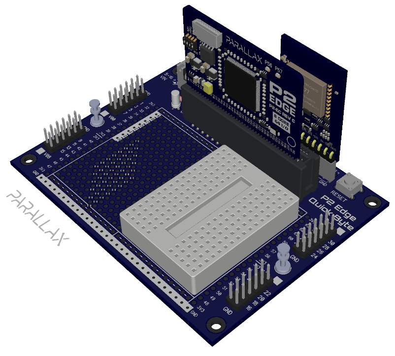
Here's a new board idea, aiming for a very low cost and simple prototyping board that would allow makers to invent, small production runs- with all IOs brought out and a WiFi socket on-board for IoT creations.
Anyone have any questions or feedback ?
This is not locked in stone yet, so feel free to suggest things you'd see added or changed.

Comments
Idea is to supply the PCB with the Edge socket pre-soldered. Then the headers/connectors would be available in an optional kit bag for customer soldering.
DC Jack could be pre-soldered, but if we left that off too then the PCB could have holes for optional 2-pin screw terminal/etc.. So customer could choose their own power connector.
Matrix supports 2x mini breadboards and surrounding female 0.1" headers for the IOs for customers wanting a compact breadboard development board
PCB dims are 4" x 3.05", with mounting holes spaced for standard Parallax robot chassis, same as PAB-WX and BOE boards.
Some 0402 footprints are between some of the proto-pads to allow a neat way to add small resistors or bypass caps, sot23, etc.. Or even just to make a solder blob easier to stick! Will see how useful (or not) those are on the prototype!
Some more images...
I'll start the ball rolling....
GND label on B R W headers should be at B not W.
The H G F E D C B A labels should be reversed along the top")
Anyway- those connect to the ABC labels beside P2 IOs 32-39 to the left of the proto area. Idea being you could jumper or install a resistor there if you wanted to use those IOs for the headers up-top, or leave them disconnected if not.
Hm, sorry to be direct.
What would be great, is a P2 module, that you can plug directly into a standard breadboard. Sacrify a few pins. Complete with USB serial and USB power supply. And all this for a reasonable competitive price, available in Europe. Yes, I would buy it, even if made not in USA..... Forget these edge modules.
Sorry again, Christof
So a FLiP2 then ?
The KISS board offers all that except for the USB data pins. That could be fixed with serial host or serial device accessory boards.
Looks like a nice board to experiment with @VonSzarvas if you already have the P2 Edge. I really like that it could be in kit form and supplied quite bare to keep costs down. That JonnyMac board is very expensive otherwise.
I also see those A-E pins make a nice 5 pin group - I could see myself wiring flying leads to those pins for VGA (with a ground).
If there was room anywhere it would be handy to have an option with a footprint for an optional USB-A connector that people could solder on and attach to the P2, sharing its signals with servo headers perhaps, although I think those pins also have LEDs on them on the Edge as well (would be ok if buffered). Doing this might allow nice little standalone setups with VGA video and USB input devices that still keeps 32 free P2 pins. In time the 32MB P2 Edge RAM could allow it to become a small dev system if it optionally supported a screen and keyboard directly, without any further header breakouts or port A I/O pins consumed for that. Another approach could be two board variants, one with servo and another with USB/VGA but if the board footprint layout was flexible and have enough room for it, a single board hopefully might be able to support either.
Also like the optional DC screw connectors too, let people decide what feeds it, not just via DC barrel jack only (plus those can be hard to desolder once fitted).
I'd like to see that design with the FLiP breadboard which offers power rails and enough space to do real work.
-- https://www.parallax.com/product/breadboard-for-propeller-flip-try-it-kit/
Good news! That FLiP breadboard fits in the space between the dual headers, and I'd expect in that configuration to use M-F jumpers for the dual header pin IOs to the breadboard.
For real work, engineers could reach for the JonnyMac, right ?")
One thing to note- an objective here was more toward the low-cost protoboard than breadboard.
The way we hope these will be priced and sold is with multi-packs, so that engineers can have an affordable way to experiment with properly soldered circuits without being concerned about costs so much, which hopefully means less time spent "tearing down" existing projects to re-use the boards.
We also "agonised" over those two footprints. Lots of pros/cons, including ... If we add them, then what else might be expected. And the P2 accessories for those sockets are already available for a low enough cost, to connect at the accessory headers. I'm adding your vote for certain this will be looked at again!
If not the footprints, maybe a 5th breakout connector pad so someone down the track could build a combo VGA+USB board for that position. I do like the idea of not tying up two existing breakout slots with the current VGA/AV and USB breakouts, especially with the 32MB Edge, as it wouldn't leave many pins free for experimenting. Having the full 32 port A pins available to play with, with other peripherals like RAM, flash, SD, VGA and USB on port B is nice and clean for applications that could make use of such a standalone platform.
It could make quite a nice standalone MicroPython setup for example with 32 free I/O and you could start hacking with right away, and you wouldn't even need a PC.
Either a vertical vga socket / usb socket on the proto area, or a breakout, looks like the instant way to go.
other options...
Could be a standard single P2 accessory socket. Only need 7 I/Os for VGA + USB so ideal. Could add an RCA socket with series cap footprint option with the last IO for an audio or composite video out. Hmm.. although, wouldn't 2x USB be expected for keyboard + mouse ?
OR.. could be a custom accessory for this board, that plugs in from the back edge and hooks into the BRW and WiFi module slots (A - H, perhaps excluding F)). I'm not a big fan of that though... it's less useful for many people I think. But it would be a simple custom board to make, and if anyone wanted a template file with that footprint we could share it.
A keyboard is potentially more useful for development and control purposes for a (text based) GUI such as MicroPython over a mouse. Right now I think the P2 USB code can actually support some (compatible) combo keyboard+mouse devices over single USB port, although one day if/when hub support is added to the P2 USB code we should be able to do more than just one device on a single port (just not quite there yet). If a new accessory board is designed for console use it might be good to use that final spare pin (after the 7 other pins are allocated) for a USB power switch, so the USB port output voltage can be shutdown if required. It will probably work better with the existing USB code that way which sort of expects that level of control AFAIK, so there's your 8 pins. Perhaps this USB power switch device implies it would need to be a separate accessory board for "console" use as you won't want to have to solder that device on the main board as well...
I‘d buy that, especially if it had external ram as well
To be a flip version you would need to use the right angle connector and plug the p2 edge in face down with the pins coming out the bottom otherwise it's not flipped.
Mike
Sorry but IMHO the KISS board is not really usable in a breadboard situation because of those dual row headers. I think a DIP board is what Christof means. (The P2 Retroblade is the closest we have to a DIP2 / FLIP2 at the moment... but that no USB either)
I will not guess who meant what. I just read what Christof said and what ManAtWork replied and the KISS board is breadboard pluggable for sure. What it lacks to fulfill Christof's requirement entirely is a usb>serial bridge on board (especially the KISS001 is very, very close). Moreover, I am yet to see a more affordable P2 board available in Europe that the KISS boards are.
Almost everything can be had but not everything at the same time.
The edge concept just does not "speak" to me at all. A cute little board but just not for me.
I took a closer look at my KISS001 board and I think it can fairly easily be modified to be very close to what @"Christof Eb." wants. The micro mini usb socket unused pins look to me to be acessible so a small, but probably not very tidy, soldering job with the ready made cp2102 or ch340 usb>uart converter on top of the board would do the trick. Im' tempted but hey, I don't really need that. Not having a usb>uart on board is a plus for me.
@VonSzarvas
Cute little board but I'm a bit concerned about the breadboard part. How reliable will it stay after a couple of uses ? Would it be a quality part or just the regular chinese made one that wears out after a few replugs ?
I can't claim to being a power user of those breadboards, but I've not had issues for the amount I use them.
For reference, it's the same mini-breadboard that all similar size Parallax boards use, including the PAB-WX, Cyber:Bot and Boe-Bot robot.
They are expected to survive a lot of rinse-repeat use in the classroom. AFAIK, they are sourced from a quality manufacturer, not the cheapest.
Those breadboards will be optional items for certain, and you can choose to stick 1 or 2 to the board. The basic package will be as a low-cost-as-possible prototyping project board. Something you can plug the expensive edge module into, and then move your edge to another project board when done.
I always remember something about my first Parallax proto board- I think it was an SX board. It was so darn expensive (for me) at the time, that I didn't want to solder anything into it, and spent a lot of time hesitating about which project to try, and I really didn't move forward as I should have!
The hope with this concept is that by moving the expensive parts (ie. the P2 Edge) into a pluggable component, then the project board can be seen as almost disposable, and creative experiments need not be stifled by the fear of soldering into a board with a P2 chip on it !
Oh, man! You have no idea how familiar I am with this approach. And I thought I was the only one to suffer this. But I don't any more.
That breadboard being optional makes total sense to me. Thanks for the explanation. Sounds like a move to the right direction.
Parallax seems to think a lot about experimenting. If you are doing temporary experiments, than this approach and perhaps for some people even the cost of the edge module might perhaps be acceptable.
If a customer wants to complete projects than he will want to buy more than one controller module. And than you will think twice, if this very expensive edge module + program adaptor + edge adaptor is really the only way to do the project. So if Parallax wants to sell more P2s than some complete board for a competitive price is needed. Price: Take this board https://de.aliexpress.com/i/32957553086.html and add these tough 17.95$ (???) for P2 instead of ESP32. Obviously boards of this size and with these features can be produced and sold for this price. (OK, at Amazon it's around 20€.) And not only by charity organisations. USB-Power, USB Serial, Audio ADC, SD-slot, 8MB Ram included. WLAN and Bluetooth will be extra. - While I think, an Audio board for P2 would make sense, this is only an example for what you can get for your $s. Something like a flip module for < €35 would make sense too.
Sorry, of course this post is only relevant, if Parallax wants to sell more P2. Forget it, if Parallax does not need younger and more customers, who help to develop libraries and help to make P2 visible.
I would welcome a complete P2 based board at the competitive price too. Sort of the C3 (P1 based) like board but I don't think that's going to happen.
Why ?
Simply because, and that is my subjective assesment only, the Parallax business model is built around the P1 and P2 chips. These unique micros are only needed to generate revenue from the associated services and accessory boards Parallax offers. The revenue generated from the chips' sales is a kind of bonus and not the main source of income. Otherwise there were much more P2 chips on the market at much lower prices and only then such a complete board could materialize, possibly at a price comparable to the cost of manufacture, to promote bare chip sales. Sadly, the Parallax is too small a company to be able to adopt this direction.
But, @"Christof Eb." , you are entirely right in saying that producing a complete board at an attractive (low but fair) price point is possible. It's just something I don't think fits in the Parallax business model so somebody else has to do it but then again, it will be difficult for that "somebody" to make a business off these boards alone.
I've said that before many times already but I do honestly think that the KISS boards (both versions) are perfect to be a permanent part of most P2 based projests. The design is straightforward, the quality is excellent and so is the price. I do not believe there will ever be one board that suits everyone's needs for every project.
We need many different boards to chose the right one from, don't we ?
I'd be very tempted to create a FLiP2, and it could be built/sold in Europe. But I wouldn't want to step on ManAtWork's toes. Seems like he already put a lot of effort into a similar concept. I ordered one this week to try it out.
For me the most tempting thing is the challenge. I created the original FLiP and remember well the challenges, both electrical and mechanical. A FLiP2 with a similar feature set to FLiP would be a high layer board count for sure, and need plenty of cunning!
Anyway-- that's super off-topic!
For the Project Board, and any board really, I always see it's another option for customers, and choice is always good.
What we try to add with the Project Board concept is the lowest-cost way for a customer to get started and try some real circuits; because there's enough space to do that.
And crucially, the bare-board price isn't inflated by so many component features for the many. Instead there's only the cost of the 80-way socket that's pre-installed, and the rest is totally optional for the customer.
One example- If you don't want to use P2 Accessories, then don't buy the expensive accessory headers! Just use the through-hole pads like any other proto-board hole, and solder parts or jumper wires as you need.
You get access to all the I/Os, and a really decent space to actually create useful circuits and products.
Sure, one board can't suit all situations, but I'd think the Project Board (especially in a 5-pack deal) would be very attractive, and grease the wheels of new opportunities.
The KISS board is more like a compact EVAL board, as it has the same header arrangement.
The closest active 0.1" P2 design to a FLiP2 would be the P2ME2, which is a simpler variant of the (now defunct?) P2D2 - P2ME2 has dual headers, original pinout, but no USB connector or link or Si5351.
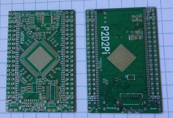
I did a P2D2Pi variant layout, that shuffled the 40 pin headers to be Pi-compatible, and made both sides also swap-compatible + other changes/additions.
It got this far :
I guess the big question on a FLiP2 is what pin-pattern to use ? For double-rows, I like the Pi-eco system pinout, as that's a global standard.
For single rows, do you drop pins, or 'go giant', but that drops customers, the bigger it gets.
Or do you go compact, and do a simple biscuit adaptor board breakout, for breadboard users ? - in that case any compact 0.1" based P2 could be used ?
Bare boards are cheap these days.
Adding a USB footprint for power has appeal, but maybe that's a bit hard for users to optionally solder ?
You could make the prop-plug the default USB-power pathway, in which case it would be nice if it does not hang-out so far ?
Looks like there may be room to have prop plug spin 90' and not extend the overall size when used ?
For a customer to get started you need to add a P2 Edge for min. 79$, a PropPlug for 18.95$, a power jack plus a power adapter for maybe 8$, this Board for maybe 19.95$. And with that you can't connect anything. Makes in total 125.90$. I would not call this lowest-cost.
The prices of Parallax products have not much to do with BOM costs. The P2 Edge Mini Breakoutboard was initally ment as low-cost way to get started with a P2 Edge, and was priced 9.95$. Since then the price was raised 2 or 3 times and now it's 29.95$. I estimate the BOM costs at about 5$.
The P2 Edge 80 pin Adapter Kit is priced at 12.95$, nothing to solder by Parallax, and a BOM price of about 2.50$.
So this will be just another P2 Edge adapter, something between the Mini Breakout and the "JonnyMac-Board", which can not be a low-cost entry into the P2. Nothing P2-Edge based can be that.
A low cost P2 Starter Board needs to be something like the P1-Quickstart, or the P1 USB-Project Board, just with a P2.
Andy
My original suggestion for a USB footprint was not for power it was USB-A for peripherals attached to the P2 I/O. If this is intended as an experimenter board it would be assumed its users are happy to solder to it. That's the point of the board being a kit and cheap, you can solder whatever you want. Of course it is a lot easier if there is a footprint already down and ready for that option. Basically it's zero cost to drill more holes if there is board space for it, so it should just about be a no-brainer IMO.
Ah, right.
Yes, Type A can come thru-hole, and quite cheap from lcsc, so a good idea to allow the footprint at least.
I see this one, very strong with 4 stakes ?

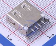

or vertical for less PCB area needed ?
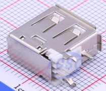
or a stronger vertical design, that looks multi-sourced
or even a right angle vertical, for minimal space ? (tho the price climbs a bit here, now 6c/100)
I'd take 100 of those for 6c")
Seriously though... we might be able to include 1 or 2 of those vertical footprints. Seems they might fit rather well. I'll grab the pattern after the weekend and see how it looks.
These seem to have mostly compatible footprints, tho I'm not sure they match the connector image photos exactly
https://datasheet.lcsc.com/lcsc/2103011234_Jing-Extension-of-the-Electronic-Co--906-461A1022D10200_C42675.pdf
https://datasheet.lcsc.com/lcsc/2103011234_Jing-Extension-of-the-Electronic-Co--906-461A1011D10200_C42671.pdf
https://datasheet.lcsc.com/lcsc/2103011234_Jing-Extension-of-the-Electronic-Co--906-351A1011D10200_C42670.pdf
https://datasheet.lcsc.com/lcsc/2103011234_Jing-Extension-of-the-Electronic-Co--906-161A1011D10200_C42679.pdf
and this group are slightly different holes
https://datasheet.lcsc.com/lcsc/2102261733_Jing-Extension-of-the-Electronic-Co--906-561A1024D10200_C39450.pdf
https://datasheet.lcsc.com/lcsc/2102261733_Jing-Extension-of-the-Electronic-Co--906-761A1014D10200_C39451.pdf
C42671 are on sale, so they are 100+ US$0.0474
I like the concept. I think it will be the best Edge board for a BLDC robot. Maybe the edge connector could be 90 deg angled and under the PCB for a more compact system?