

Advice for board layout
 ke4pjw
Posts: 1,334
ke4pjw
Posts: 1,334
in Propeller 2
I have come to the point in my light controller project that I need to layout a custom board, and I am seeking advice.
I use ExpressPCB for layout. All of my previous layout experience has been through-hole, with only one board that had a SMT component. I have a component for the P2, with the pad for a heatsink/ground.
What should I take into consideration?
- Should I choose a multi-layer design? What is common?
- What do I need to know about stencils?
- What should I do to minimize power supply components? I would like a simple, clean power design. 100% OK with linear components.
- What is the best way to populate the boards for a prototype quantity?
I am really excited to grow into thinking differently about board design.
--Terry
Comments
Well that's exciting, Terry
I think the key thing to keep in mind is that you need to iterate to get to a product, and there's no perfect way to get there, particularly with parts shortages being thrown into the equation. Everyone spends way too much time thinking about pcbs, given how cheap they are to get made
I'd start with getting up to speed with SMT techniques using the PCB software you're already comfortable with, because SMD introduces a whole heap of new packages and jargon that is confusing at first.
Unless you're doing something miserly, or maybe running from a sub 5v supply (lipo?), you're going to want a switching 1v8 regulator before too long, or a big heatsink, or fan cooling. There are 1v8 switchers in TO-220 style packs, so if you design for a TO-220 you can always fit either option
For stencils - the ones from oshstencils are probably a good starting place if you're in the US. Being clear polyimide they're easier to line up than the stainless ones. If you do move onto ordering stainless stencils from China, tell them to cut your stencils down to something like 15x15cm. If you go with the defaults they ship a rigid ~25x35cm flat second parcel that attracts a lot of extra shipping charge, for no good reason. If you shrink it ("custom stencil size option on the websites"), then it just goes in the same box with the pcbs.
You don't have to go 4 layer to get started, I'd worry about the other aspects first, and go 4 layer at the onset of ground bounce issues or higher current requirements.
Finally, I did use ExpressPCB years ago and its nice way to get started, but later on you're going to end up in something like Kicad, which has a lot of really nice features, and the ability to preview your boards in 3D. Kicad has 'handsolder' component footprints for things like resistors and capacitors, which are like normal (say 0603 or 0805) footprints, but with bigger pads to make soldering with an iron/pencil easier. There's a learning curve with a few bumps along the way, but overall its a good way to go. There's a Kicad book by Peter Dalmaris from Tech explorations that is quite useful, in that it goes beyond just the software, and covers ordering of pcbs (etc). I'm fairly used to making pcbs but still found it really useful on half a dozen occasions
What MHz do you think you will need ?
You will need at least 2 layers, but 2/4/6 is more a choice of density vs cost.
4 layers allows quite solid ground plane, and good thermal spread.
Some designs route on 2 layers and allow an option for 2 inner planes, that are not mandatory for operation. You can then prototype / prove on 2 layers.
Linear parts are simpler, but they do add thermal limits to the overall design, and they also impose supply range limits.
They are ok for designs not pushing P2 MHz - note the P2 Edge chose SMPS on both 3v3 and 1v8, to allow wide Vcc tolerance.
Is PCB size is not a concern, you can throw larger packages and more copper spreading at linear regulators, but because generally designers worry about energy and size, you will find that linear regulators of 2A+ region, are niche parts with not a huge range of choice. (ie they are being phased out over time)
On older parts, PowerGood is also less common.
If we look for 2A or better 1v8 regulators :
eg AZ1084CD-1.8TRG1 shows up as stocked at Mouser, 2A rated, 33c/100, that's a common part family number
or you can go newer and thin, and get QFN20 NCV59745AMW180 $1.38/100
or maybe NCP5663DS18G, from 98c/100 from Rochester - 3A 5 pin D2PAK with Power Good.
or NCV5661DT18RKG / NCP5661DT18RKG in smaller DPAK5 1.5A typ Ipk
Addit: If your MHz allows a relax to lower peak ICC, you can get more choice in the 1-2A zone.")
When using linear regulators, you can also series them, to spread the thermal footprints. If layout allows, the tabs on those should be furthest away from P2, as you want to avoid the regulators heating the p2
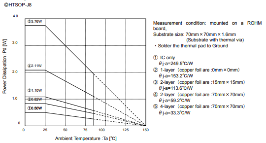
Further to this, I see ROHM has some good data showing 2 or 4 layer PCB differences, in direct power handling terms.
This is their thin, exposed pad SO8 (eg BD18HC5WEFJ 1.5A 1.8V )
and this is their 'thin DPAK' HRP5 9.395 mm x 10.540 mm x 2.005 mm (eg BA18DD0WHFP, BD18FD0WHFP )
Most important advice: Buy all your parts before starting the layout or even the schematic. It occured several times that a distributor has listed 10k+ parts in stock and when I finished the layout there were zero available.
If you run the P2 with 200MHz or less and you don't have many critical signals like external memory buses you probably only need 2 layers. You can swap IO pins until you get a "star topology" with almost all traces on the top layer and only very little and short crossing bridges at the bottom so you still have an almost solid ground plane. However, the routing of two supply "rings" (1.8 and 3.3V) will be a little hard with only 2 layers.
Hi @ke4pjw. I am in a similar situation to you and am currently laying out my first P2 based board.
I have done a few P1 based boards using Express PCB and they worked well but one had complex split inner layers and I found it very hard to prove these layers were connected correctly with Express PCB, so have decided to move to Kicad6 for this new board as the Design Rules Checker seem to make this sort of verification easier. My board will be 4 layers, and I have already bought my parts, some with the greatest difficulty as @ManAtWork suggested.
I have been looking at laying out the power rails and in particular the decoupling capacitors around the P2.
I looked at the P2Edge Board schematic and it uses 4.7uF ceramic caps for all the P2 decoupling caps.
Now, I was expecting the more normal 0.1uF capacitor and have noted a few other boards here in this forum seem to use 0.1uF with a larger reservoir capacitor near the regulator which seems fairly normal to me.
My question is what decoupling capacitors should I be using?
Am I missing something and should I be using larger decoupling capacitors with the P2 for some reason, the P2 edge seems to work OK with the 4.7uF caps? Any thoughts appreciated.
Regarding rules checker for ExpressPCB: https://forums.parallax.com/discussion/156063/expresspcb-board-checker-program#latest
The link contained the first post still works.
The caps could be 0.1uF or 4.7uF
The important thing to know with each capacitor package size (as far as power bypass & decoupling goes) is that the largest capacitance value in the same package size is best. In the mix comes cost issues, which is why 4.7uF was used as it strikes the right balance. For example, 10uF 0402 caps are still too expensive.
One key advantage of the distributed 4.7uF caps is that they all provide towards bulk capacitance on the voltage plane, so additional larger sized (and larger capacitance) caps are not required. Which is quite important on high density boards! The impact of the DC Bias effect is also negated somewhat.
0.1uF is a really old "standard", and is based on caps being darn expensive back in the day, and crucially, being physically larger. If you were using 0805 caps then you'd certainly consider using 0.1uF. Without looking at the capacitor datasheet I'd expect something close to 0.1uF to be necessary for such a large package size. But with 0402 you can take advantage of the larger capacitance value.
If you visit one of the capacitor manufacturer sites and pull up a characteristics chart for any 1uF (for example) capacitor in 0402, 0603 and 0805 sizes. Then compare the three charts, you will see the difference the package size makes to the inductance and impedance. Here's one example : https://ds.murata.co.jp/simsurfing/index.html?lcid=en-us
Generally as the capacitor package size increases, the series inductance also increases proportionally. And as the capacitance increases, the AC impedance will fall.
Sorry, but I must disagree with you. 0.1uF (100nF) do a different job than bulk 4.7uF capacitors. They bypass high frequency switching spikes. In fact 0.01uF can do a better job for the highest frequencies, but are used in addition to 0.1uF, not as a substitute.
There are other things that come into play too, such as dielectric and size, and of course pcb layout.
All I can recommend is to look at the datasheets and keep in mind the context and frequencies involved.
When it comes to inductance, package size is far more significant than capacitance.
So I had powersupply components selected......and now you can't get them.
Are there any "jellybean" (ubiquitous part available from multiple vendors) 1.8V switching regulators?
Wish there was ! At least at the lower price points it feels like those things change with the wind.
You probably found something by now, but I was just looking at these so copy/pasting:
Von,
Unless you order 3000 of that part through Digikey you won't be able to get any.
https://octopart.com shows that Rochester Electronics has them or $0.93 a piece.... https://www.rocelec.com/part/TISTPS62141RGTR
Be careful though .... that foot print I wouldn't want to wish upon anyone. It's not easy to solder to unless you have the right equipment.
It may be possible to get the bulk qty from Rochester which is 326 (i believe?)
You now need to read the fine print at digikey to see where the stock really is.
There are a lot of switching regulators in the Sot-23 package format, perhaps thats the smart way to design for maximum flexibility, given the shortages
With current supply issues being what they are, we have had to design with multiple options where depending on availability, some parts of a board may or may not get populated from the board house.
Here is a recent example and it happened to be a voltage regulator problem. During my initial schematic design I source the availability of all of my components in a design. In this particular case the supplier had 6 or 7 thousand regulators. I only needed 100 for a particular build. A week later and those 6 or 7 thousand regulators were the dreaded "ZERO IN STOCK" with 52 weeks lead time. To put this in more perspective, when I have ordered those same regulators before, the numbers I am used to seeing were in the neighborhood of 120 to 150 thousand. So while 6 or 7 thousand may 'seem' like a lot and there are plenty available, don't be fooled. Fortunately I found another regulator, but it had a different footprint and slight variations of supporting components. So ... There are two places on the PCB to accept a regulator depending on what may be available. Sure it makes the PCB real estate bigger, but this is what we have to do right now.
Switching regulator 4.5..16V input, 0.6 to Vin 2A output, SOT23-6, high efficiency, no diode required, 23k+ in stock: https://lcsc.com/product-detail/DC-DC-Converters_SHOUDING-SD8942_C250795.html
Linear regulator, 1.8 or 3.3 output, SOT23-5, low noise, 29k+ in stock: https://lcsc.com/search?q=SPX3819
Thanks for the comments further up about the capacitor size, good discussion @VonSzarvas & @Cluso99 .
I am a bit old school and was taught similar things to @Cluso99, of course the Multi-layer capacitors simply didn't exist then, they seem to be more complex beasts than I imagined.
I will check out the data sheets for the different package sizes as suggested.
Thank you!
I ordered up 100 of the switchers. ( SD8942) I guess we will see how they work out.