

From Egg Beater to Egg Painter??? - Build a P2 EggBot?
 Christof Eb.
Posts: 1,539
Christof Eb.
Posts: 1,539
in Propeller 2
Hi,
it might be just the right time to build an EggBot, based on P2?
My version is planned to be based on
- Kiss Board
- A4988 Step Motor Drivers.
- Taqoz Forth for interaction and VGA graphics. Graphics for supervision. Forth is supposed to allow fast software development and time is running.....
- The idea is to generate the patterns on the fly and "inside P2" for example on base of fractals. Give those other cogs some work, while one is controlling the steppers.
The mechanics are already there: 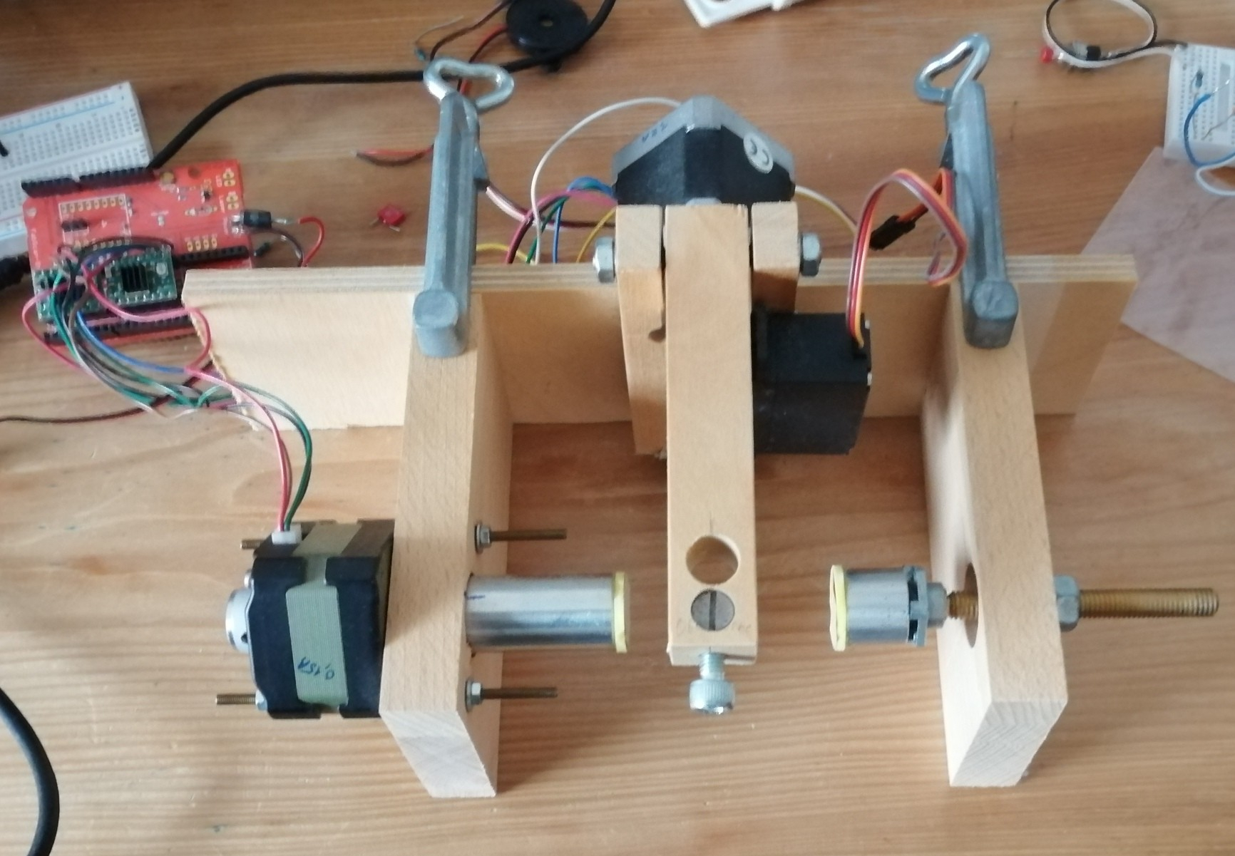
Perhaps this is some idea to join in?
Have fun, Christof
Comments
Lemniscates.
I found them in an old magazine from Australia about TRS-80. March 1982. It is for Basic Level II. https://www.classic-computers.org.nz/system-80/micro80/Micro-80-Volume-03-Issue-04-(1982)opt.pdf Page 25 and page 34.
There are 2 parameters per picture. The authors then said: "You will be surprised by the variety of effects. "
The parameters are generated by random for each "tile". To generate the ornaments directly on P2 is very straight forward.
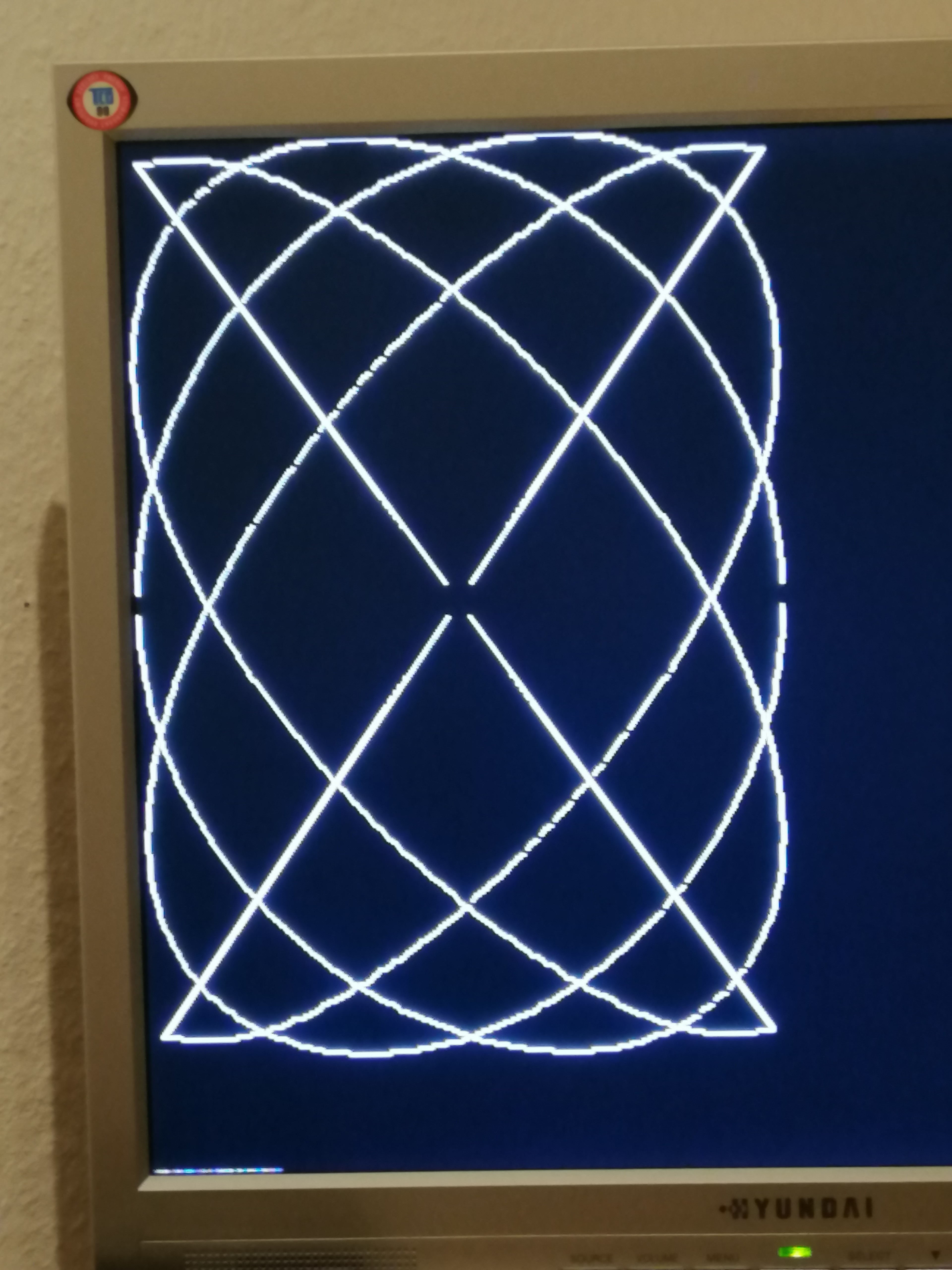
It is great to have ( VGA ) graphics as output of P2, helped me debugging and optimising.
Very first Eggs:
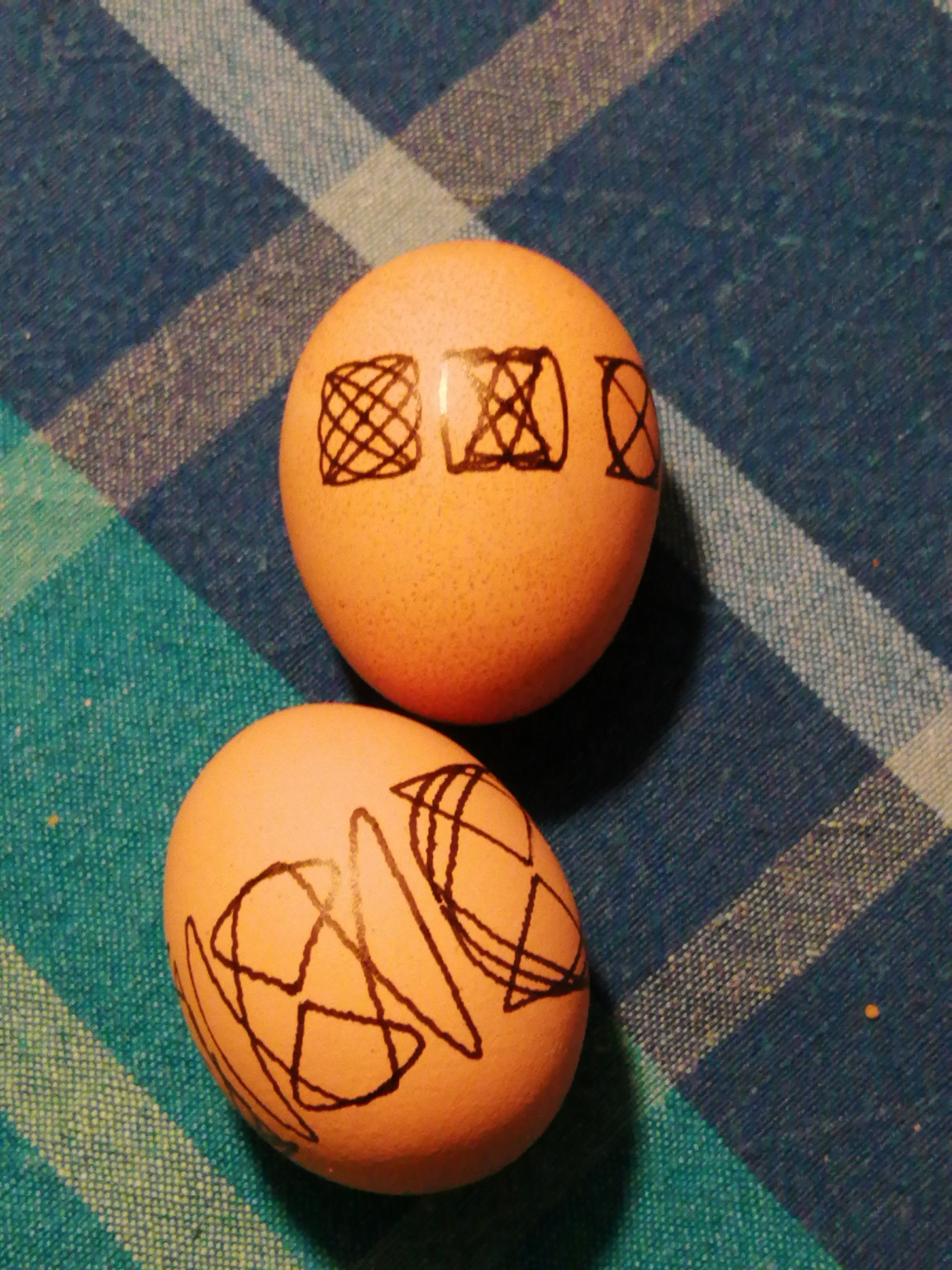
Next I will try 3 rows of even smaller "tiles" of lemniscates.
Egg plötter... what a time to be alive.
Yes, just fun. These are boiled eggs, so these will vanish after some days. No harm done. Last year I treated some cookies with my laser engraver. This worked too. Unfortunately they tasted something like burned somehow. They did not vanish. :-(
One interesting thing is the computer generated pattern here. It shall be "nice". So how to make something nice under computer control?
*Symmetry
*Repeating a theme
*Variations, otherwise boring
*Good Proportions like "Goldener Schnitt"
*?
Some other possibilities seem to include some of these characteristics
https://mathematikalpha.de/wp-content/uploads/2016/12/16-Chaostheorie.pdf
Other thoughts?
Hmm, the patterns look very dithering. I think this could easily be improved by microstepping or adding gears and increasing the resolution.
Hmm, yes these "dithering steps" are not ideal. This was using the 16* microstep mode of A4988.
If I used full steps and watched the axis with very slow steps, then I can see, that one of the motors does steps with uneven angles.
Tried a lot of things: Resolder, other motor of same type. The full steps are more even now. But with this the dithering was still visible.
It seems, that the chosen current was too low for this motor. The microsteps did not move the motor, that moves the arm, with even steps. So I experimented with higher current.
Unfortunately now at least one pin of P2 seems to be damaged. Perhaps it got some spike, when I pushed up the current?
Lemniscate Eggs!
Taqoz Forth source code included. - Which is not pretty, perhaps it still is some sort of inspiration for somebody...
Ok, then it must be some sort of slip-stick effect. The motor acts like a "magnetic spring". The torque rises with the actual rotor position diverging from the angle of the magnetic field. If the threshold of the static friction is exceeded the rotor slips to its new position until it's stuck again with static friction.
The solution would be either decreasing static friction (easy at the bearings but not really possible at the pen tip) or increasing motor torque. The latter can be achieved with a bigger motor, higher current or a gearbox.
Thanks for this comment! It helped me realize, that due to the spring effect, you need higher current, if you use microstepping for higher resolution, because the divergence of position is very much smaller.
It turned out, that fortunately only the driver module was damaged and not P2. :-) So I replaced the module and set high currents for the motors.
Actually I do not really understand the datasheet of one of the motors. https://hsmr.cc/uploads/Projekte/Tandon%20KP4M2-203%20Schrittmotor.pdf
It says I.phase= 0,15A, V=12V and R=37,5 Ohms. As I*R= 5.6V these values must be related to some unknown speed? I=0,15 A seems to be a rather low value, the motor does not become warm outside.
Perhaps this type of motor is not really suitable for microstepping because it was designed for voltage drive instead of current drive.
Perhaps someone can say something about this question: Can I damage the motor due to overcurrent with a magnetic field that is too strong for the magnets or is the limit over-temperature of the winding?
I'd recomend a motor with winding current between 1 and 2A. This motors have a winding resistance of several (<10) ohms and can be driven from a 24V supply in constant current mode, meaning taht the actual (average) voltage at low speed is only a few volts and there is headroom for BEMF at higher RPM.
You can but that question is rather theoretical. It would require a current of something around 3 to 5 times the nominal current AND an angle divergence of more than 90°. If you let the rotor follow the magnetic field (no or low torque) the field of the permanent magnets is always in-line with the field of the stator windings so no de-magnetisation can occur. And with a current >3 times the nominal current you burn the windings of a small motor rather quickly.
BTW, neodymium magnets also demagnetise due to heat. At 80°C you can feel them becoming weaker. That effect is reversible at the beginning. But if they get too hot (over the curie temperature) it becomes irreversible.
So I was wondering to find another "nice" pattern. It seems, that symmetry and repeating is so important here, that almost anything is looking "nice", if you mirror it twice and repeat modified patterns....
This is generated:
Generate one random number per pattern.
Use the lower 16 bits to decide for the 4*4 matrix , if a + is printed or a blank.
mirror x
mirror y
Happy Easter! Christof
GIF, has to be opened:
An Easter Game Of Life.")
....so this would be a good day to get started with those eggs again?!
Still enough time to build the setup, if you want to join in....
Well, let's see, if I can get this machine moving again. And then we need some fresh patterns.
I started cooking some eggs this morning. Found my mechanical setup with stepper drivers. Soldered some pins on a fresh Kiss board.
My old notes of documentation should have been better...
Have fun, Christof
Yes yes yes!! Looking forward to your Eggtastic creations!
Got it working again.
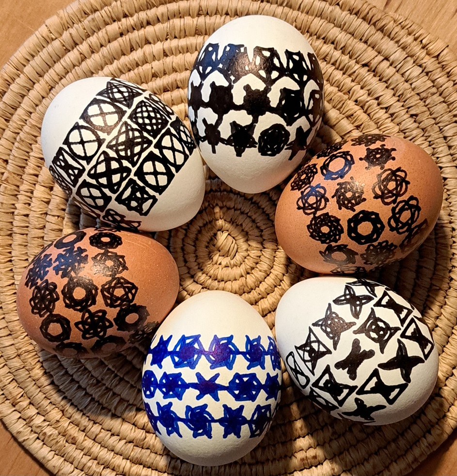
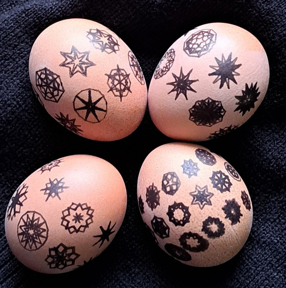
The one at 10 a clock is the original "Lemniscates", which take the basic curve and mirror it twice.
The brown eggs are my actual favourites. They take a slightly modified curve and rotate it for 5 to 8 spurts.
This is all about the cordic machine, qrotate! Rotate a pattern without floating point math. :-)
One egg has 3*12 patterns and needs about 15 minutes.
At first I had thought, that I don't need a monitor output. But when I started to try new patterns, I realized, how very helpful here VGA graphics are. If I had them not, I would be forced to have a separate program running at the PC.
Christof
That is pretty neat, thanks for posting this!
Makes me wonder what else could do... Laser engraving? Would that work?
Maybe Red then Blue then Green colors to make images?
What are you using here BTW, permanent marker? Some probably goes through the shell, right?
Hi,
yes this is "Lumocolor permanent" pen by Staedtler and similar. And yes the color bleeds through sometimes.
Laser engraving would be difficult, at least with my laser, because it's depth of focus is very small and it's low power. These natural eggs are not that precise in detail. Of course only for emptied eggs.
There are people, who do very nice mechanical engraving. Which is very nice, light shining through.
Perhaps etching might be possible?
When i had my first trials with this mechanical setup some years ago, the goal was indeed to plot pictures. The software could do HPGL. One colour only. There is the constraint, that the picture must be something like placative, because the tip of the pen is not too fine. Therefore it is not so easy to find suitable pictures. And it is a lot of work for every single picture.
These "Lemniscates" can be "created" by P2, you only have to work out some good parameters, like scale, limits for number of rotation, limits for the length of the curve,.... Then each pattern is unique and each egg is unique. There are some patterns, which are more beautiful than others. If you have a lot of patterns on an egg, then the less interesting ones make the "better" ones something to discover for the viewer, which is fun.
This would be a cool thing to show my kids for sure....
Might have to take a day off to copy this...
What boards do you have there for the stepper motor control?
Hi,
this uses a carrier board: https://github.com/watterott/FabScan-Shield/blob/master/hardware/FabScan-Shield_v11.pdf
because I had it.
There are those modules or similar on it: https://www.parallax.com/product/a4988-stepper-motor-driver-carrier-board-black-edition/
16x Microsteps
If I would redo mechanics, I would thrive for low inertia of the arm and use stronger step motors.
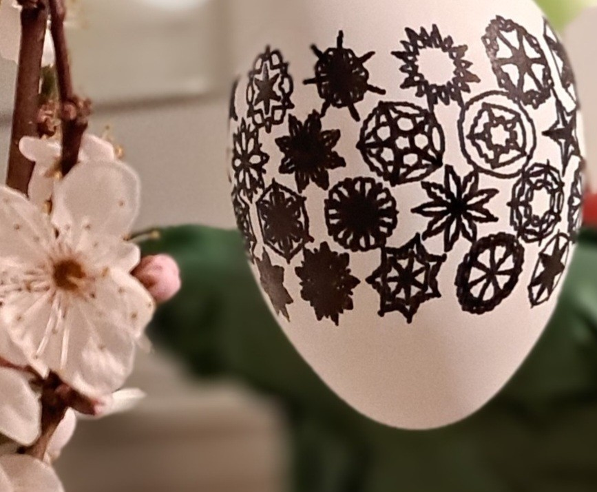
Todays edition is Mandala Stars:
I was looking for something to do over spring break and this might be it!
Dug up an ancient Zen CNC. This thing was supposed to be one of the first 3D printers, but it was pretty bad at that.
Been sitting on a shelf for a dozen years...
But, this might be its moment to shine")
Propellerized it today and have X, Y, and Z axis working.
There one more axis controller that can use for spinning the egg.
Think I just need to find a stepper motor and 3D print some stuff and it's done?
... for the automatic Pattern Generator I have added Bezier Curves. Two types:
Either with a tangent parallel to a circle, or to a line through centre.
https://en.wikipedia.org/wiki/De_Casteljau's_algorithm
Some inspiration came from here: https://pypi.org/project/RandomMandala/
Math, on the funny side:
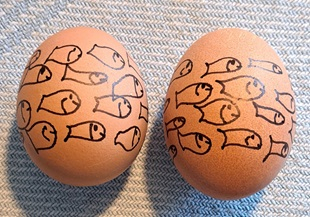
Bezier curves define a fish pattern, which is modulated with varying random numbers.