

propeller FLiP ESC PWM on pin 31 vs GPIO pins
 jomarchrid
Posts: 6
jomarchrid
Posts: 6
in Propeller 1
Hey everyone,
I'm currently having an issue with getting a pulse signal to work on any other pin. I use simpleIDE since I'm more comfortable working in c++.
So here is my "debug" code:
`int main() // Main function
{
low(16);
set_direction(16,1);
while(1){
pulse_out(16,1200);
}
}`
So let me outline my issue:
- The ESC is connected to any GPIO (example pin 16).
- Plug in the ESC to battery.
- Run the "debug" code and nothing happens.
However, when I follow this procedure it somehow works:
- The ESC is connected to pin 31.
- Plug in the ESC to battery.
- Run the "debug" code using pin 31 instead and the ESC runs.
- Switch the ESC to pin 16
- Run the "debug" code using pin 16 and the ESC still runs.
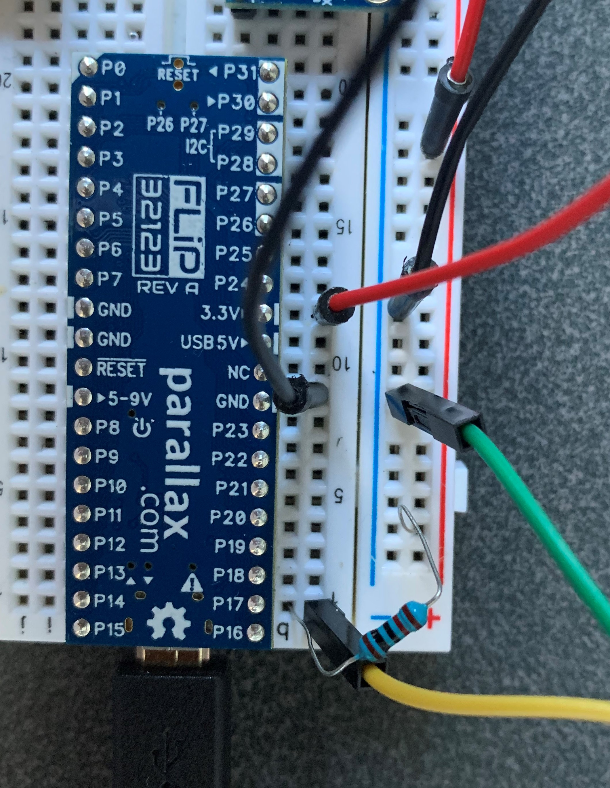
I did a bit of reading on the FLiP and noticed that it has a 10k pull-up resistor to 3.3 V so I tried that. I'm assuming there is something unique about pin 31 but I just can't put my finger on it. Below is an image of my wiring.
- A 10k resistor is placed on pin 16 to 3.3V.
- Yellow goes to signal of ESC
- Green goes to ground of ESC
Comments
Welcome to the propeller,
I didn't have a chance to try your code that should kind of work but here is some more info.
Pins 30, 31 are used for loading code from the serial terminal. So these pins are already setup before they hit your code.
Pin 16 is floating when you set the direction to output which should then be low but code be high.
pulse_out will generate either a high pulse or a low pulse based on the state of the pin before the pulse_out.
Most ESC's run at 400hz which means there is a pause between pulses to the ESC. With your while loop the pulse may look continues.
low(16);

while (1)
{
  pulse_out(16, 1200);
  pause(4);
}
Mike
Thanks Mike.
Ill fix that part up in my while loop. I did a bit of playing around with it today and managed to figure it out. I realized the ESCs don’t respond or “wake up” unless the start signal is at 1000 microseconds. I’m guessing that somehow pins 30 and 31 are sending such a signal
Those pins are for programming and debugging and should not be used for general IO. Likewise, pins 28 and 29 connect to the EEPROM and should connect to anything but I2C devices.
I'm not much of a C programmer, but you need to have a delay between your pulses. If the ESC is expecting a standard RC servo pulse input, you can add a delay after the pulse. I would use about 18 milliseconds to give you about a 20ms loop.