

Booting from flash on the P2
 rogloh
Posts: 6,414
rogloh
Posts: 6,414
Is a 47k pullup resistor sufficient on P61 to get the P2 booting from SPI flash or is something else required?
I have a Winbond SPI flash chip (W25Q128JVSIM) installed on my board with a 47k pullup resistor on the CS pin (P2 IO pin P61), and the other 3 SPI flash pins are connected directly through to the P2 with no other pullups or pulldowns and no SD socket fitted etc. I can see the SPI flash from the P2 and can erase and write to it and dump it out and it looks like it takes the binary, but at this stage it doesn't seem to let me boot my P2 binary application from it (still testing that). Maybe I've overlooked something simple or there is another issue for me to resolve.
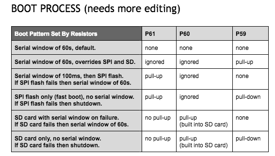
I noticed that the P2-EVAL board uses a 10k pullup while mine was 47k. Should the actual pullup resistance used matter here in the boot detection routine? Hoping not.
Comments
I wondered if I had some internal board resistance on P59 pulling it up. But TAQOZ seems to say they are floating except for P61 (as expected). So it seems okay.
Hmm, this is strange.
I have created a simple program to toggle an LED on both the P2-EVAL (pin 56) and my own board (pin 31).
CON
  _clkfreq = 160000000

PUB begin
    repeat
        pintoggle(31)
        pintoggle(56)
        waitms(500)
This creates a short binary with flexspin:
I then flash both the boards (P2-EVAL and my board) with this same binary using this type of command (and also changing the serial port name for my own board):
After flashing, the P2-EVAL starts up and blinks the LED after reset, while mine does nothing. Downloading into RAM first to verify the code had worked fine on both boards.
When I used JohnnyMac's flash explorer program I captured the interesting range of flash addresses and diffed them between both boards. I only saw data differences right after the led binary which I am presuming was just the last 512 bytes of random P2 RAM that got flashed at the end of the program along with the code and that would have differed on both boards.
I still can't figure out how my board won't boot this code from flash. A CRC/checksum corruption perhaps? Probing these P2/Flash SPI pins will be a nightmare in circuit as the signals are sandwiched between two boards, though I probably could try with the P2ME2 removed and booting standalone. At least the CS pin would indicate flash boot activity.
So I found I was looking in the wrong area. At startup my AVR supervisor micro (propplug replacement) was doing something funky with its TX output into the P2's RX pin and it looked like it could be held low at boot time in some cases and I think this must have been preventing the bootup from flash. When I modified this pin control portion of the AVR code, flash boot on my P2ME2 suddenly started working.
I still need to figure out exactly in what logical order all these pin control changes are happening but this adjustment certainly allowed it boot from flash while it wouldn't work before. I know I need to drive this signal low at times to ensure it doesn't parasitically drive the P2 when it is powered off. I probably just need better co-ordination with the P2 reset and its powering and shutdown sequence.
P.S. Wow. Loving how fast this thing boots from flash... press the power on button and LCD outputs something immediately. Beat that, Raspi.
Found out the hard way the directions are unclear and you have to flip a switch on the eval board for the Propeller Tool to be able to program the flash. There is no real reference to this in any of the documentation but there is one cryptic chart that shows what switch needs flipped. Personally, as an equipment developer myself I deal with this a lot, incomplete documentation cause user errors 99% of the time.
I was able to bypass the switch requirement with FlexProp and it would program the flash without an issue which made the problem appear to be the Propeller Tool when it was not.
Might have something to do with your problem.