

Dual encoder RS-485 rec. board
 Scroungre
Posts: 161
Scroungre
Posts: 161
Anyone else want one of these?
It’s a dual-encoder RS-485 receiver board. From left to right (on the board):
1) Two industry-standard encoder connectors, 10-pin DIH at 0.1” spacing
2) Decoupling caps
3) Six RS-485 termination resistors.
4) Two RS-485 line receiver chips
5) Decoupling caps
6) Twelve resistors in six voltage dividers to make 3.3V signals
7) A handy connector for a couple of pushbuttons
8) More caps
9) An external 5V power connector (or use a jumper)
10) Pull-up resistors for the pushbuttons (but no other debouncing)
11) Connector to the P2 development board(s). 12-pin female, mounted on the underside.
For software, I intend to use (maybe modified a bit) Jon McPhalen’s excellent quadrature code.
I want a few, so I’m going to build some, but I was curious if anyone else wanted any, and if there were anything else they think would be nice to put on it. So far I have not ordered any boards, and most of the parts I happen to have in stock already.
Obviously, it’s not a tiny board – it’s 4.25” long and nearly 1” wide, two layers. I could make it much smaller by using surface-mount components; I laid it out ‘old school’. Nothing here should be high-frequency; if your encoder wants to run over a MHz or so, this might not be not the board for you. It also doesn’t have any separate mounts – it’ll flap around a lot unless it has some support at the left end.
Another way to make it smaller would be to ignore the Index signals. That would mean the board only needs one line receiver, and a third of the resistors go away. Does anyone care about Index? I don’t, really, but it might come in handy. I have also had trouble with cross-talk when two different encoders were using the same receiver chip. I never conclusively proved it was the chip (it shouldn’t have been!), but a revised board that used separate chips for each encoder didn’t have that problem.
Optical encoders can be power-hungry beasts, so I provided the option for external 5VDC power. Otherwise you can just put a jumper on the External Power connector to connect Internal 5V (from the P2 board) to the 5V on this encoder board.
Files posted for illustrative purposes. If anyone cares, I can post the actual PCB files (CadSoft’s Eagle, rev. 7.6), although the silkscreen on the PCB is a colossal mess at the moment. I’ll build and test a couple and then post ‘final’ files. Component values are TBD for now. I’ll put the whole thing under the MIT license, unless someone has a better idea.
Questions and commentary invited! Thanks, S.
Comments
Definitely interested, Scroungre. I've got some boards for interfacing to RS485 due this week, happy to share what I'm up to
Do you have a link to the encoders you're using?
Any reason to not have used something like a 74HC4050 instead of the divider?
3486 version
@ Tubular: No link to the encoders, I'm afraid - I'm using out-of-production Computer Optical ones that I happen to have a lot of. They were supposed to be 'compatible but better" to HP encoders, and now I'm not sure that HP is even building optical encoders anymore.
@ Mickster: A 74HC4050 would probably work fine too. Cost a bit more, take up less board space, easier to install. Toss-up, I suppose. I even have a few 4050's around.
Also, that's mildly interesting in that I didn't provide any signal forcing for when there isn't an encoder plugged in. Hmm. Another rack of resistors might be in order, along the lines of the 16k's in your schematic.
I did force the inputs of the unused section of the line receiver, though - that's recommended by some manufacturers. Of course, with thru-hole chips, I can install sockets, and simply remove the line rec.'s for when I don't want a channel.
@ All: Can I depend upon the P2 smart pins for pullup resistors on the "pushbuttons"? Save a couple there, at least. I've done a few AVR boards, and even though those chips have programmable pullups too, it seems to make things more reliable on powerup if you use external ones.
S.
Ok, interesting about the HP encoders.
You can definitely rely on the internal resistors for pulling up/down the pushbuttons, the trick is simply to "output a high" with 1k5/15k/150k resistance in your code, before you sample the same input to see whether the button has been pressed or not. As long as this happens in order in your code in sequence I can't see any power up issues
That's because HP spun off much of its original core businesses as Agilent in 1999, keeping the compute and printer divisions.
Then Agilent further divided itself up in 2005, putting the optical chips into Avago.
Avago subsequently merged with Broadcom in 2016. I think that's where these parts now reside.
Cool. So I ripped them out. Actually, I ripped out ALL the resistors! Wheee...
I wanted to have the 'encoder line keeper' resistors as per Mickster's schematic, as well as the line terminators, but really didn't want to make the board even longer so I thought SIP resistor networks would be just the dot.
I used 8-pin ones throughout, both bussed and discrete, although that does leave me with a few spare resistors loitering about. Mostly because it looks prettier when they're all uniform, and I happen to have a lot more selection of 8-pin networks than 6-pin networks in my junk collection. The layout is a bit less tidy, although still nicely compact.
Now the board is significantly shorter (3.3") and just a bit wider (0.95") mostly so I could run heavy power traces down the outside edges. I like doing that with two-layer boards. Have a new picture., and thanks for your remarks! S.
You are correct. Digikey even stocks some, still with the old HP part numbers(! (HEDL, HEDS series), although the ones I was looking at did not have differential drive. The Broadcom AEDC series has it as an option, but isn't in stock at Digikey. Perhaps a vendor more into motion control would have a better selection. S.
Credit goes to Wikipedia for those dates. And the Broadcom deal was new to me too.
I tried my hand at soldering sop-16 by hand, turned out ok, maybe some solder wick would clean them up some...
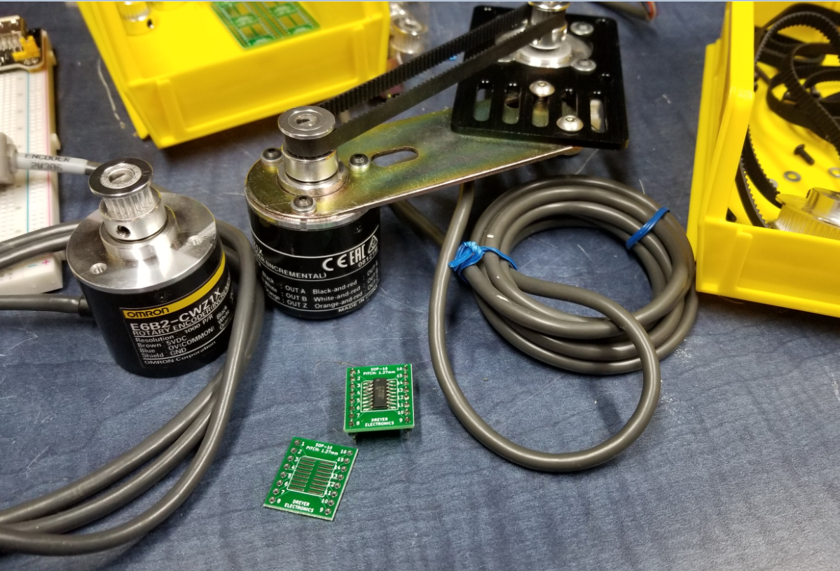
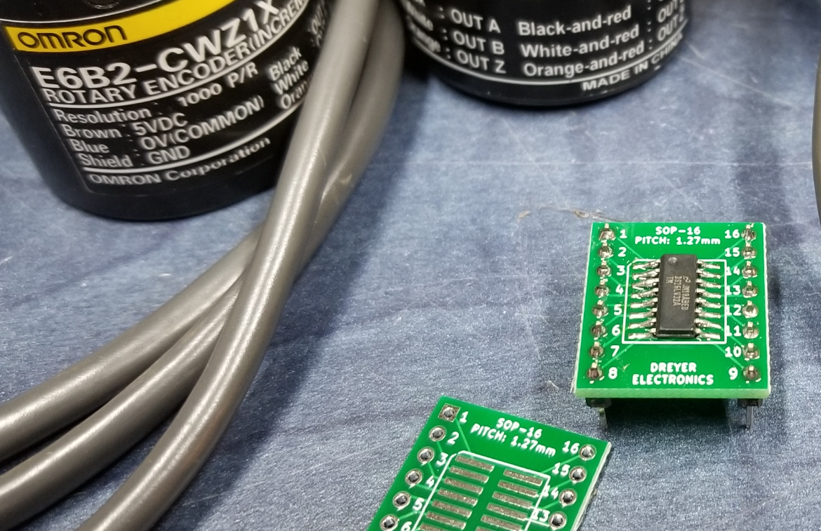
I used the DS26LV32A line receiver chip because it can be powered by 3.3v and outputs 3.3v.
I've used the AM26LS32A in the past with these encoders, so the low voltage version of the same chip seemed like a safe bet.
These Omron E6B2 encoders can be bought on aliexpress for around $20.
I've also found mounting brackets for them cheap also.... and brackets for stepper motors... and pulleys and belts...
There's an interesting thought. Instead of running a buffer (a 4050 or something) at 3.3, run the line receivers at 3.3V - then you can throw the voltage dividers away also. That's keen!
Unfortunately the 75173s that I was going to use are not specified to run at less than 4.75. Still, definitely worth considering for a board that's intended to use new parts instead of 'What can Scroungre find in his junk box?' (There's a reason I go by 'Scroungre'!) S.
Good call
Many thanks
@Scroungre (and anyone else)
Terminating resistors:
I use the typical 120R on my RS422/485 networks and I realise that some datasheets recommend this for encoders but I don't know what to think because I have big-ticket Galil Motion Controllers (spec'd at up 15M counts/sec) that don't have this. Many of my cable-runs exceed 10 meters, with no problems. Granted, high-quality, low-capacitance cabling is always used. I wonder if they consider that loading-up the channels is more of a problem than cable-capacitance(?)
@ Mickster
I'm in two minds on this too. The specs say 'Terminate!' yet I too have had systems run fine for years without them, and yes, 10 meter or longer cables in some horrible industrial environments (although not at 15MHz (!!) Mine don't do that...). One of the beautiful bits of using resistor networks is that they too can be socketed - and you can pull and put whatever values you like with very little faffing about. Good for experimentation! S.
PS - Reminds me of days before the turn of the century, fiddling with termination of SCSI chains on Amigas and Macintoshes. Whee?