

TAQOZ - how to instantiate (and talk to) separate SPI and I2C busses ?

Say, I need an additional SPI bus to talk to the SPI device and I do not want to use the one that is used for the boot memory, be it a flash or an SD card, and I also need a separate I2C bus for high speed I2C devices to not slow them down because of the other, not so fast ones sitting on the same bus.
How do I do it ?
I know I need to set up pins and buffers and clock speeds and assign them properly. Anything else ?
EDIT: Moderator, please move this thread to the Propeller2 section where it belongs. I don't know how to do this. Thanks
Comments
Oops. Just realised you’re referring to TAQOZ so Peter will need to answer specifically.
Unless your driver specifically can handle multiple ports (unlikely except for multiport serial) you will need another copy of the driver.
The Flash SPI and SD Drivers will likely be different anyways, so you will just use both and give them different pins.
You will also need an I2C driver. Possibly @JonnyMac has one already.
TAQOZ handles multiple SPI and I2C ports at various speeds easily. No need for "drivers".
There is no reason why you can't use the existing I2C pins though as there is no problem mixing speeds there and in fact the speed varies from 100kHz for device scanning, to 400kHz for normal use, and up to more than 3MHz for the UB3 chip. However there is the routine
I2CPINS ( scl sda -- )with which you can select other pins dynamically within the same cog or perhaps another cog just needs a dedicated bus etc. I2C speeds can be changed to 1MHz by saying1000 I2C.KHZ.NOTE: You don't need pullups on the pins as these are automatically enabled and I prefer the internal 1k5 for high speed operation.
Same too with the SPI bus, you can select pins on the fly with
SPIPINS ( &cs.mi.mo.ck -- )and this routine is also used by SDPINS which as you can now guess selects the SD card pins as needed, meaning we could have 8 SD cards connected for instance. The SPI pins are specified with a single long using what I call decimal byte notation, the same as is used for IP addresses. In this mode every group of decimal digits represents a single byte and so with 4 bytes we have 4 parameters specifying the CS MISO MOSI SCK. You can also use bcd notation too with : separators and no prefix.If CS=32, SCK=33, MOSI=34, MISO=35 then
&32.35.34.33 SPIPINSor32:35:34:33 SPIPINS.Just checking this notation:
For example the P2PAL module has a PSRAM and it is selected with
&53.49.48.52 SPIPINSSPI supports slower buses and normally runs at about 1/8 of the clock speed which means over 20MHz for 200MHz clock. The routines support slower speeds but I will have to patch that back in again as I haven't needed to.
Perhaps I should use a single long as well for I2CPINS just for conformity.
BTW, when you use SPIPINS it sets up the pins as inputs and outputs with the clock low. All the routines clock by toggling the pin so if you want a high or low clock, just drive the clock high or low for the idle state.
edit: THE TALKING TO PART - I almost forgot. Here's a quick list:
To write a byte use SPIWB ( SPI write byte) and it will left justify it to send it msb first. Use SPIWW SPIWM and SPIWL for 16, 24, and 32 bits respectively. The CE is selected automatically and you need to use SPICE to disable it when you are done. SPITX ( src bytes -- ) for when you need to transmit an array of bytes and SPIRX ( dst cnt -- ) likewise.
The SPIRx routines are a little different in that they add to whatever is on the stack already so to read a byte you need an initial value. For instance when the PSRAM needs to read 16-bits it uses this routine:
pub SPIRW 0 SPIRD 0 SPIRD 8<< OR ;As MJB would say, read the source code. Have a look at the SPIRAM section in EXTEND to see how this works in action.
Some interactive scope captures taken at 200MHz using P24..27.
&27.26.25.24 SPIPINSTransmit a single byte then deselect
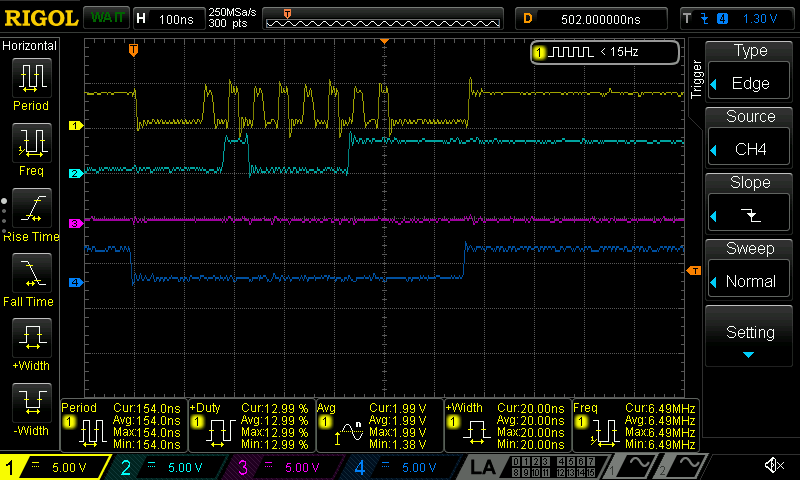
$43 SPIWB SPICEThe clock frequency is over 20Mhz and more importantly symmetrical.When you need to transfer a byte array such as 512 bytes for a sector etc, then use SPITX or SPITXE if you want it to enable the chip select.
Or just transmit a long from msb to lsb.
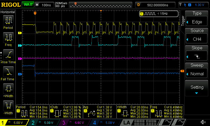
$12345678 SPIWLWith all of the TAQOZ built in smarts it almost seems like a walk in a park. That information is more than I need. That basically means I can connect pretty much anything SPI or I2C and talk to it as I please. WOW.
BTW, MJB is absolutely right. Reading the source code and learning from it is a good practice. The thing is, sometimes it's just hard for me to understand the clever tricks the code wizards use to get things done.
Thread moved to P2 as requested.
This thread has been moved from the P2 category to ForthSpace and will continue here.