

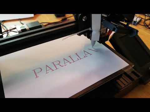
P2 GRBL printing text on a Creality Ender3 with a red sharpie....
 mwroberts
Posts: 87
mwroberts
Posts: 87
I've added a lot of functionality to my GRBL program this past month.
I bought a Creality Ender3 v2 and zip tied a red sharpie to it to make ... a plotter?
A cheap arduino stepper motor shield wires directly to the Creality stepper motors, the plugs fit.
I wired the normally open limits to some p2 pins and set the pull up resistors for the pins in the program.
Homing works. Limits are working. G-code files can be read in as text to DAT, then streamed out, if you want to do that, instead of using a G-code sender. The serial text handler/parser cog is non-blocking code.
If at any time it receives a "?" it needs to send out current position data. Any text coming in needs to be parsed and potentially put in the move buffer. That's why Home() is in 3 stages... it loads 3 or 4 moves in the buffer, then returns. In AutoCycle() you can see where I am working on embedding variables into the G-code string that will go to the move buffer... maybe a Spiral Demo next? AutoCycle needs more thought to make sure it is non-blocking, like using global variables, if it's (AutoCycle()) local variables get lost when it exits then reenters...


edit: 4/10/2024 Handles comment lines from UGS better... added StepBasePin in constants section rev f
edit: 3/27/2024 jog was still messing up... fixed with new d rev
edit: 3/26/2024 jog was messing up absolute coordinates... fixed in new_b rev
edit: 3/22/2024 added jog functionality
edit: New version of UGS asks for GRBL sw version, a "$I" request, I needed to add it to the parser.
jm_fullduplexserial needed to be updated to latest version because of "field" and "fdec" being
reserved for prop tool now.
Comments
Very cool! Just as a pet project, I started to port grbl to spin2 early last year. I don't think I ever really intended to see it through to completion - just see what it would be like to port such a massive project to another language. I haven't touched it in quite awhile. Awesome to see a workalike actually working though! I think that's definitely a more sensible way to do it, if one is serious about getting a spin version working.
Excellent work. This something that is very much needed to both show off what the P2 can do and that is a real world application. I would pay money for something like this !!!
That is great!
Now all we need is a carrier board - One end has a P2Edge Connector and the other the headers to plug in a RAMPS board (the version compatable with the DUE which is 3.3V).
Instant small P2 CNC controller that could also run a 3d printer.
Now attach a pen with water-resistant ink and glue a blank PCB to the printer's bed,")
@mwroberts thanks for pointing me to this newer version!
The newest version of UGS asks for GRBL software version when trying to connect... a "$I" request, that my parser wasn't handling, so I added it in and it now connects to UGS.
I had to swap in the newest jm_fullduplexserial also because of "field" and "fdec" errors...
Thanks! Hoping to test this out this weekend...
Looks like you are pushing the marker tip onto the paper? I'm thinking about doing more like a diamond drag type thing....
Hi,
there is no need to move the pen in a parallel way. In my setup it is moving along a 80mm radius. It is good to avoid backlash for the movement. I use 2 ball bearings and some pretension on those bearings. The arm puts about 10...35 grams weight onto the tip of the pen in addition to the weight of the pen of about 8 grams.
@mwroberts Thanks for providing this. Seems to connect with UGS.
Thinking I'm going to have to change the pins I'm using. Looks like you are using P0..P7 with a basepin setting of 0.
I see a note about a change to indirect addressing, but not how the pins are actually assigned.
From the commented out legacy code, I'm guessing it's like this:
          P0   pXstep
          P1   pXdir
          P2   pYstep
          P3   pYdir
          P4   pZstep
          P5   pZdir
          P6   pAstep
          P7   pAdir
Is this right?
My controller boards also have enable inputs that I have to drive low.
I can probably just add that to main() ...
BTW: Should Jog from UGS work? Doesn't seem to ...
@Rayman
In the DAT table is a variable called basepin. It is set to 0 so I use 0,1 for X step/dir, 2,3 for Y step/dir etc... Change the value of base pin to whatever you need.
Jog doesn't work.
You can type in g1 x10.0f10.0 in the text box in ugs and it will execute the single line of g-code...
Ok, I got it moving! Some progress.
But, amount of movement is not what it should be and seems too slow.
I see a note about not having millimeter to inch conversion.
Does that mean that we pretend inches are millimeters?
Or, should it actually move the amount it says?
This has 0.9 degree stepper motors and dip switches set for 1/2 stepping...
Also, lead screws are 1.25 mm per turn.
Pretty sure I have to adjust the code for this somewhere...
I think this is what I need to change, but not sure about the format:
    ParGrbl[100] := 80_000   '1_000_000 x steps/mm 1000.000
    ParFmt[100] := 3
    Pnum[22] := 100

    ParGrbl[101] := 80_000   'y steps/mm 1000.000
    ParFmt[101] := 3
    Pnum[23] := 101

    ParGrbl[102] := 1_000_000   'z steps/mm 1000.000
    ParFmt[102] := 3
    Pnum[24] := 102
Actually, think figured out now, since UGS is saying:
$100 = 640.000 (X-axis travel resolution, step/mm)
$101 = 640.000 (Y-axis travel resolution, step/mm)
$102 = 640.000 (Z-axis travel resolution, step/mm)
Which is correct... So the above is steps/mm * 1000, now set to 640_000 for all three axis.
Ok, Z seems correct, if I assume UGS display has units of mm.
But, X and Y only move about 1 mm when I say to move 10 mm...
Ok, think I have it now, had to change x and y to match Z here:
Seems I need to figure out how to invert the Z axis too...
@Rayman
In the DAT table directionality can be set by modifying the variable "DirBits".... bit 0 is x direction, bit 1 is y direction, etc...
Thanks!
I guess my last question might be about starting a job and setting the zero position...
How do you do this?
Manually with gcode and then restarting the P2 once it's at the starting position?
Or, is there some gcode command that works to reset position to zero?
I think if you type "G92 X0.0" it will zero out X... "G92X0Y0Z0A0" should zero all axis...
feedrate override should work from UGS also.
Ok great, thanks.
Thinking about what to add in now...
One thing is USB keyboard and another is some kind of display.
Thinking that could be useful for jogging and setting zero.
Also, I see you have it rigged to be able to use gcode from files.
So, don't need PC to do repetitive jobs...
The display could provide feedback and progress for that...
@mwroberts Thanks for posting the code and your help, this is great!
BTW: How would you implement an emergency stop?
Stopping the assembly cog should do it, right?
This app has a function to help calibrate GRBL based (And hopefully GRBL workalikes). It guides you through the measurement procedure, and tells you what to put in which variable. Shouldn't be too hard to figure out how to use it with this.
https://play.google.com/store/apps/details?id=com.jodyreimers.millrightcnc&pli=1
@Rayman
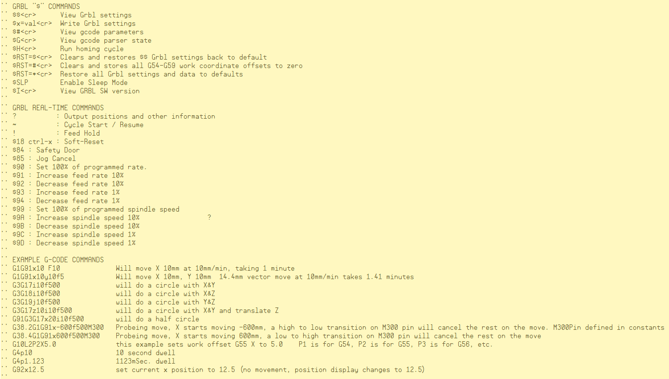
! will feed hold
~ will resume
ctrl-x will soft reset and halt the program like an e-stop with the axis positions preserved.
Take a look at the "Home()" method. It feeds in g-code probing moves that cancel motion on a switch trigger. You can make your own method that sends whatever
G-code over that you want.
Look at the "AutoCycle()" method. It shows how to place variables into G-code moves and send it to the interpolator....
In order to mimic the GRBL parameter setting capabilities, like if you send to GRBL " $100=80000", GRBL stores that setting in flash so it is set even if you cycle power.
To do that on the propeller I would need to write it to onboard flash or sd card, and that's tricky. So, the GRBL parameter style setup isn't working yet.
I know Chip has some new software to utilize the leftover onboard flash that would be perfect for this. @ManAtWork also has some simple flash routines I have used...
I plan to post my latest P2 GRBL soon. It does pulse generation in a very different way, and the step/dir pulse width timing is set at 1uSec. (not parasitized yet)
which is good for A4988 but DRV8825 needs 2uSec min pulse width. It has a debug user interface I was playing with where you can type in a g-code line in a text box and send it over to the P2 GRBL. I was also working on jog buttons in the debug user interface... And a way to send a text file that the P2 reads on startup to the interpolator controlled by the debug user interface.
Do you have limit/home/reference switches on your machine and do you plan on using them to "home" or "Reference"?
Thanks!
There are some limit switches, and would be nice to use them at some point. Only have for home now, but want to add limits too.
So, the main thing I need to add is the fourth, A, axis for rotation. Is this implemented here? I think so.
Have to figure out how to specify angle instead of distance for rotation...
Chip's flash code is very nice and easy to use. Think latest is in OBEX.
I don't think I'm doing anything different to make it a rotary axis.
Set the Ascale variable so that a "G1G91A360.0F3600" command rotates 1 revolution.
We can add code if we need to display rollover on A.
I will see what we can do to get the 4th axis to show up on the UGS display.
Why not use the smart pins to generate step pulses? If you use NCO frequency mode the duty cycle is always 50%. So you never have to worry about the pulse width. If the frequency is not above 250kHz (period > 4us) then the pulse width is always >2us.
@Rayman
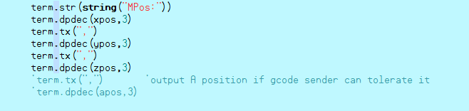
Uncomment the these two lines in "RealTimeStatus()" and the A axis will show up in the latest UGS version.
@ManAtWork
I'm using lots of smartpins!!!

In my latest GRBL
In NCO duty cycle my base period is 1uSec. If I set it to 2uSec it would work and I would have to double the Y "velocity" adder that would be added 500,000/sec instead of 1,000,000/sec.
I'll have to think about if NCO frequency mode would work here...
Thanks I'll try A axis soon.
@mwroberts Does your creality ender have 5V logic interface like my thing does? I guess the original Arduino boards are 5V logic. Mine works at 3.3 V anyway though.
If so, are you using some kind of level changer or just using direct from P2 pins to stepper drivers?
@mwroberts I'm not 100% UGS is the best thing for the egg painter. Probably the right thing for cookie painting though.
So, seems possible to create a custom code to send gcode commands to this P2 GRBL.
It's just a serial text stream, right?
Is there special handshaking to get started or does it just start ready to go?
Also, what if anything does P2 emit over serial?
Does UGS use some special gcode command to inquire about current status?
I think it must, right, from the "RealTimeStatus()" code you posted above...
Also, I think I'm seeing P2 send over all the settings to UGS on startup. Don't think it actually uses that though, right? Just prints in the console...
@Rayman
I drove my creality stepper motors with this setup... you can see it in the pictures... it's logic will run on 3.3v and is super cheap...
https://www.amazon.com/Haosie-Extension-Stepper-Engraver-Printer/dp/B0C6X9VVKM/ref=sr_1_13_sspa?
Yes, serial text stream... open parallax serial terminal to talk to it... type a "?" and enter to get a position and status reply... may need to set PST up for both carrage return and line feed when you press enter
The "!" halts the motion without a 10,13 (ascii carriage return and line feed)...
The"~" will restart the motion...
It might use some of that stuff the GRBL sends over, like work offsets, but I don't think you need to worry about any of it.