

Connecting P2 to the RPi0/Ultibo [now on Github]
 pik33
Posts: 2,419
pik33
Posts: 2,419
I created a github repository for this: https://github.com/pik33/ultibo-propeller/
A proof of concept.
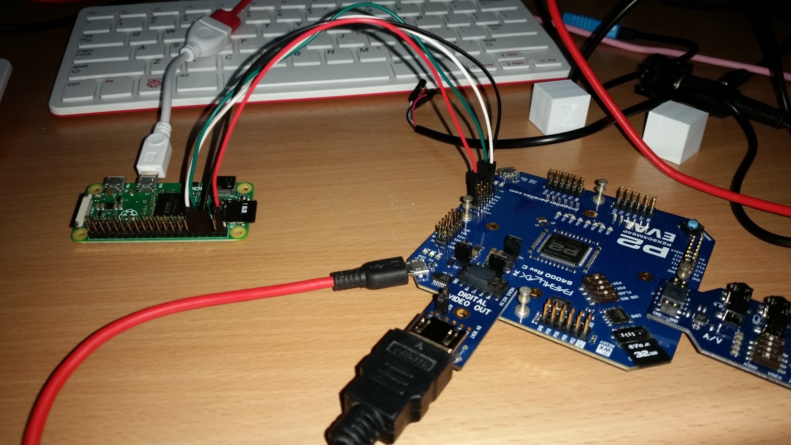
I have a idle Pi 0 in my drawer. I want to connect a keyboard and a mouse to a P2. The existing driver cannot see the small RPi keyboard so I have to use a big one.
The workaround:
- connect a Pi 0 via serial port to a P2
- connect the mini RPi keyboard to a Pi Zero
- connect the mouse via a hub in the RPi keyboard
- program the RPi to receive keyboard and mouse events, send them via serial port to the P2.
I used Ultibo to program RPi so no linux was abused in the project and the Pi starts near as fast as a P2
To test this:
- unpack
- copy the Rpi stuff (4 files) to the FAT32 card and insert into Zero
- connect the RPi to a P2 (I used +5V GND,P32,P33 - RPi gets power from P2 Eval board 5V line - it works even when P2 board is powered via PC USB)
- connect a keyboard and mouse to the Zero
- compile the P2 stuff and connect it to the HDMI monitor
- move the mouse, press keys, look at the reports
I will make a github project out of this to make the rpi source available, but this needs cleaning first.
All kind of interesting stuff can be done that way: RPi can be a memory, a coprocessor, a mass storage, etc.
Comments
Nice going Pik33
Another interesting aspect is enabling the P2 access to Rpi camera (or perhaps even webcams)
Yes faster booting bare metal type RasPi's could allow them to be used as peripherals ready to work after only very short startup/reset delays.
I quite like the idea of a RasPi Zero as a cheap+fast mass storage device if the 4 bit SD mode drivers are already part of Ultibo. Are they? Also USB sticks may be readable this way until P2 native code is ready for that application.
As far as I know even Linux uses 1-bit interface in RPi so (not 100% sure) this is 1-bit. But then all USB mass storage devices are supported (pendrives, HDD, SSD) Eth port is supported too, but no wifi. The graphic chip is supported, so OpenGL ES is available. I wrote drivers for camera and audio and recompiled mad mp3 library and xmp module player for it. Then I wrote a SID emulator and made a player (mp3/mod/sid/wav)
Ultibo allows in 4-core RPis to free a core from all the system stuff and have a "dedicated core" for your own code. In theory you can free 3 of them, as far as I know nobody tried this.
There is full low-level access to the framebuffer device with a video scaler, so RPi can be used also as a "graphics card" including vblank synchronization and low level timings settings.
Still, the RPi chip has a complex internal bus which causes a jitter on GPIO pins. Yhe jitter is lowest in one-core Pis so bitbanging a parallel bus can be done better using a Zero.
I am thinking about installing a Zero inside a RPi keyboard to make the P2 keuboard/mass storage interface. I don't know how fast I can run the serial port: I set 19200 for the kbd demo which is enough for this, but way too slow for a mass storage.
@pik33 if the speeds are too slow you could investigate SMI - see this:
https://iosoft.blog/2020/07/16/raspberry-pi-smi/
A good double wide breakout for P2 would allow access to 8-9 bit SMI, SPI, I2C and serial on the Pi. Very versatile and handy for experimenting.
It seems the SMI is worth trying. I need some free time. The speed can be enough to use the Pi as a video ram or a mass storage device.
The Pi has no analog capabilities and limited real time capabilities while having a lot of RAM and raw computing power. The P2 is excellent at real time, it has very good DACs and good ADCs, but it has not enough RAM and no floating point. Connect both of them with a fast bus and we have all in one.
Now it works @ 1920000 bps and recognizes all needed keyboard and mouse events: mouse move in 1024x576 range, mouse wheel, mouse keys, click, doubleclick, key pressed with scancode and charcode reported, key released, key modifiers (ctrl,alt, shift, etc) pressed/released
A base for the P2 and RPi Zero boards is being printed now to improve the safety
A github repository added: https://github.com/pik33/ultibo-propeller/
To compile RPi Zero part, you have to install Ultibo environment, but there is kernel and 3 necessary firmware files in the repository.
Good work. I had a browse through the Ultibo source and I think the SD card driver stuff buried within is probably actually supporting the 4 bit mode. But man my Pascal is really rusty nowadays; it used to be my language of choice way back when. These days it just looks so verbose and hard to wade through.
If the Ultibo SD card support really is 4 bit, and the interface speed to the P2 is boosted with SMI for example, then it might be a quick-n-dirty/easy way to get even faster SD access speeds on the P2 in really high speed applications until something can be developed for the P2 in 4 bit SD mode. SMI sort of burns a COG always waiting for control via the Pi strobes though and has to be carefully synchronized with reading/writing P2 hub data (probably via the FIFO).
Even if it is 1 bit, there is a filesystem ready. A pendrive or SSD can be connected. I will dedicate a cog for the communication. First the serial, as it is enough for keyboard/mouse. As in a old PC, now the keyboard has its owm "microcontroller" (now the RPi which is a "computer" became a microcontroller for a microcontroller, which became a "computer"...) . Second, i2s. I have i2s code partially readu for Ultibo, so I have to do this for a P2. This will allow audio transmission from Zero to P2. Third, the SMI. This will allow all the stuff above and many more.
A contraption")
There is of course a P2 board. On the left a keyboard/mouse controller (=Raspberry Pi Zero), on the right a MIDI controller (Sparkfun Arduino MIDI shield https://www.sparkfun.com/products/12898 )
The midi shield was expensive but available from a local provider. I had a trouble with Amazon where I tried to buy much cheaper board: after 3 weeks waiting they at least returned my money back. No more Amazon The Sparkfun board has 2 potentiometers. 3 buttons, 2 LEDs and, of course, 2 MIDI sockets. No problem with connecting a controller and receiving messages: the standard serial procedures work. I don't know if I can send somethng via MIDI out: the board is intended to be powered from 5V instead of 3V3 I connected to it.
You could disconnect MIDI IN and then power it with 5V. The driver should reliably recognize the 3V3 level coming in & lift it to the required 5V. For full duplex use a level shifter.
I cannot power the board with 5V as it will fry the P2. This 5V powers not only MIDI: it also powers buttons and potentiometers. I can only hope the midi devices I have will sense the signal which is weaker than it should be. As I want the P2 to be a synthesizer controlled by a controller (synthless) keyboard (Novation Impulse 61) the MIDI In is what I really needed and this works. I will check the MIDI out later: I have a MIDI synth, too.
I can always add an Arduino to the project. I have several of them too.
The board can be powered with 5V when you don’t feed any incoming data to the P2. Thus my suggestion to remove the MIDI IN. Then you can see if you produce correct midi out. Just to rule out the voltage level is the cause for trouble.
Alternatively you can build this: https://www.instructables.com/PiMiDi-A-Raspberry-Pi-Midi-Box-or-How-I-Learned-to/
The PI is also 3V3.
It is likely that the chip(s) used on the midi board require 5V and may not work with 3V3, just as the P2 will not work with 5V as it will destroy the P2. So you are left with interfacing them. For this, if you want help, you will need to attach the schematic of the midi board (makes it easier for those here willing to help) and be careful of the advice you get. Many think they know, but fewer actually have the knowledge to give proper advice.
This is the schematic: http://cdn.sparkfun.com/datasheets/Dev/Arduino/Shields/Midi_Shieldv15.pdf
This is the driver: https://www.diodes.com/assets/Datasheets/74AHC1G125.pdf
While it works with 3V3 or 5V I was incorrect assuming it’s logic levels would allow for 3V3 to be recognized as high.
I shouldn’t have assumed, but made sure. Apologies for causing confusion.
The instructibles project I mentioned does the level shifting due to the double inverted Schmitt trigger use, and I have this circuit on my bench using a P1 and it puts outs the required 5V from the midi standard.
While the P2 would be right on the minimum drive edge for the 74AHC1G125, you would find that it will in fact work reliably.
Feeding the P2 from the opto 6N138 would require a series resistor for protection. You would be safer with a pair of resistors as a voltage divider and 1K and 2K2 would be perfect for this.
The 74AHC chip should work at 3V3. The problem may be 220 Ohm resistors which reduce the current to 5 mA and if it will not work because of too low current, the simplest modification may be shorting one of them.