

PLL settings calculator
 cgracey
Posts: 14,297
cgracey
Posts: 14,297
in Propeller 2
In getting Spin2 going, I realized it would be really nice to just be able to set the clock frequency using 'CON _clkfreq = 250_000_000' and let the compiler work out the details, on the assumption there's a 20MHz crystal, which could be overridden by an _xinfreq declaration;
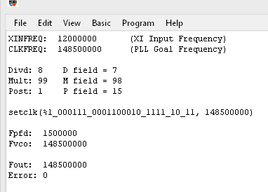
I spent all night working out the details of this PLL settings calculator. It favors low crystal divisors (to maintain high Fpfd), never lets Fpfd frop below 250KHz, and keeps the VCO between 99MHz and 201MHz, unless the frequency called for is higher than that. It's not that complicated and has a search space of 1,024 possibilities.
I wrote it in SmallBASIC and now that the concept is proven, I can implement it in the compiler. Here's the SmallBASIC code:
You can set the xinfreq and clkfreq values and it will come up with optimal PLL settings. Here is some output. SmallBASIC doesn't let me copy the screen text, so I had to do a screenshot:
I spent all night working out the details of this PLL settings calculator. It favors low crystal divisors (to maintain high Fpfd), never lets Fpfd frop below 250KHz, and keeps the VCO between 99MHz and 201MHz, unless the frequency called for is higher than that. It's not that complicated and has a search space of 1,024 possibilities.
I wrote it in SmallBASIC and now that the concept is proven, I can implement it in the compiler. Here's the SmallBASIC code:
xinfreq =  12000000
clkfreq = 148500000

error = 1e9
for pppp = 0 to 15
  if pppp = 0 then post = 1 else post = pppp * 2
    for divd = 64 to 1 step -1
      Fpfd = round(xinfreq / divd)
      mult = round(clkfreq * post / Fpfd)
      Fvco = Fpfd * mult
      Fout = round(Fvco / post)
      e = abs(Fout - clkfreq)
      if (e <= error) and (Fpfd >= 250000) and (mult <= 1024) and (Fvco > 99e6) and ((Fvco <= 201e6) or (Fvco <= clkfreq + 1e6)) then
        result_divd = divd
        result_mult = mult
        result_post = post
        result_pppp = (pppp-1) & 15 '%1111 = /1, %0000..%1110 = /2..30
        result_Fpfd = Fpfd
        result_Fvco = Fvco
        result_Fout = Fout
        error = e
      endif
    next
next

print "XINFREQ:  "; xinfreq, "  (XI Input Frequency)"
print "CLKFREQ:  "; clkfreq, "  (PLL Goal Frequency)"
print
print "Divd: "; result_divd, "D field = "; result_divd-1
print "Mult: "; result_mult, "M field = "; result_mult-1
print "Post: "; result_post, "P field = "; result_pppp
print
print "setclk(%1_";
print right(bin(result_divd-1),6); "_";
print right(bin(result_mult-1),10); "_";
print right(bin(result_pppp),4); "_10_11, "; clkfreq; ")"
print
print "Fpfd:  "; result_Fpfd
print "Fvco:  "; result_Fvco
print
print "Fout:  "; result_Fout
print "Error: "; result_Fout - clkfreq
You can set the xinfreq and clkfreq values and it will come up with optimal PLL settings. Here is some output. SmallBASIC doesn't let me copy the screen text, so I had to do a screenshot:
Comments
con
  _clkfreq = 320_000_000

pub go
  repeat
    pinnot(16)
I've got the Spin2 interpreter lodged into PNut.exe now, so F12 compiles and downloads Spin code. I made a quick list of all the things I need to do to get it set up right, but I got sidetracked on this PLL thing all night.
I think it was ozpropdev who came up with the code I use that includes:
Maybe _XDIV might be nice to still play around with?
But, actually, I guess one could just restart the clock in assembly if one wanted to explore different settings...
Does the listing file include the report above ?
Also, it can be useful to allow users to specify the error threshold, and to have the search software function report all found values (_XDIV _XMUL _XDIVP) < given error
Sometimes jitter matters more than absolute precision, or users may be wanting to do some margin testing.
#
# Chip Gracey's PLL settings calculator in Python3
#
#

xinfreq =  12000000
clkfreq = 148500000

error = 0x1e9

def right(value, count):
    # To get right part of string, use negative first index in slice.
    return value[-count:]

for pppp in range(0,15,1):
  if pppp == 0:
    post = 1
  else:
    post = pppp * 2

  for divd in range(64,1,-1):
    Fpfd = round(xinfreq / divd)
    mult = round(clkfreq * post / Fpfd)
    Fvco = Fpfd * mult
    Fout = round(Fvco / post)
    e = abs(Fout - clkfreq)

    if (e <= error) and (Fpfd >= 250000) and (mult <= 1024) and (Fvco > 99e6) and ((Fvco <= 201e6) or (Fvco <= clkfreq + 1e6)):
      result_divd = divd
      result_mult = mult
      result_post = post
# '%1111 = /1, %0000..%1110 = /2..30
      result_pppp = (pppp-1) & 15
      result_Fpfd = Fpfd
      result_Fvco = Fvco
      result_Fout = Fout
      error = e

print("XINFREQ:  ", xinfreq, "  (XI Input Frequency)")
print("CLKFREQ:  ", clkfreq, "  (PLL Goal Frequency)")
print("Divd: ", result_divd, " D field = ", result_divd - 1)
print("Mult: ", result_mult, "M field = ", result_mult - 1)
print("Post: ", result_post, " P field = ", result_pppp)
print()
print("setclk(%1_" + format(result_divd-1,'06b') + "_" + format(result_mult-1,'010b') + "_" + format(result_pppp,'04b') + "_10_11, " + str(clkfreq) + ")")
print()
print("Fpfd:  ", result_Fpfd)
print("Fvco:  ", result_Fvco)
print()
print("Fout:  ", result_Fout)
print("Error: ", result_Fout - clkfreq)
dgately
EDIT: Obviously, my modifying "clk_mode" variable isn't correct for Chip's fully calculated version. It would be a case of replacing the four instructions of "replace old with new ..." with a simple "MOV clk_mode, result_clkmode" instead.
Here is the PLL calculator in 80386 that is inside the compiler now:
Man, the forum software hides things when it sees two @ symbols together.
ModEdit: Code attached in a txt file
Only one of these schemes at a time is acceptable to the compiler. It checks to make sure valid label sets are in the user's code and then acts accordingly.
Whoops! I accidentally edited your post instead of quoting it...
It would have to be an object to be so, unless I made it part of the interpreter.
FYI.. That issue is top of the list to be resolved, and need not be an issue much longer.
As a quick solution, the code has been attached as a text file to your post above.
> cgracey wrote: »
>
>
> Man, the forum software hides things when it sees two @ symbols together.
>
>
>
>
> FYI.. That issue is top of the list to be resolved, and need not be an issue much longer.
>
> As a quick solution, the code has been attached as a text file to your post above.
Thanks. I noticed earlier that sometimes, rather than quote a message, it would just put '>' signs in front of each paragraph.
I'd been trying to figure out the source of that, and I think I just found the issue in the same plugin that's spoiling the [@ @] chars (and a bunch of other char combos). Thanks for mentioning it, as I wasn't entirely sure if that's something you were deliberately doing !
Anyone needing a runtime change need only include and call it?
> @cgracey , what is the default _clkfreq to use if only _xtlfreq or _xinfreq is given?
You need to assign a value to _xtlfreq or _xinfreq and that value becomes clkfreq. Also, clkmode is set to %1110 or %1010 for _xtlfreq or %0110 for _xinfreq. There is no default clkfreq value for those cases.
The previous clkmode must be known in order to safely switch away from it. That value is always kept in Spin2, so there's never a chance of the clkmode being unknown. Well, if a programmer didn't use the CLKSET instruction and just did a HUBSET, that would cause the value to become unknown.
If you switch clocks you have to wait until both clocks are high (or both are low) to avoid glitches. So when you switch from a faster clock to a slower one it sometimes takes more than serveral clock cycles of the faster one. If the PLLs is switched off before the clock switchover is completed then the processor hangs. This could have been avoided if PLL shutdown had been delayed until after switchover was sucessful. But I guess this wasn't implemented in the current silicon.
It just locks the current clock state (0/1) and then waits for the new source to transition to the same state before switching over to it.
The whole thing worked fine until I added a divide-by-one PLL output mode which bypassed the post-divider. When deselected, it glitches before the clock switcher grabs hold of the current state. Now, in case you are using the divide-by-one mode, you need to keep the PLL mode bits in the same state while switching to another clock source. This means you need to keep a copy of the current clock mode in RAM somewhere that you can employ to switch the clock mode later.
You need to switch from PLL mode to RCFAST mode while keeping the same PLL mode bits.
In Spin2, this is all taken care of automatically with a SETCLK(mode,freq) instruction.
xinfreq =   20000000
clkfreq =  333333333
errfreq =     100000

error = errfreq
for pppp = 0 to 15
  if pppp = 0 then post = 1 else post = pppp * 2
  for divd = 64 to 1 step -1
    Fpfd = round(xinfreq / divd)
    mult = round(clkfreq * (post * divd) / xinfreq)
    Fvco = round(xinfreq * mult / divd)
    Fout = round(Fvco / post)
    e = abs(Fout - clkfreq)
    if (e <= error) and (Fpfd >= 250000) and (mult <= 1024) and (Fvco >= 99e6) and ((Fvco <= 201e6) or (Fvco <= clkfreq + errfreq)) then
      result_divd = divd
      result_mult = mult
      result_post = post
      result_pppp = (pppp-1) & 15 '%1111 = /1, %0000..%1110 = /2..30
      result_Fpfd = Fpfd
      result_Fvco = Fvco
      result_Fout = Fout
      error = e
    endif
  next
next

print "XINFREQ:  "; xinfreq, "  (XI Input Frequency)"
print "CLKFREQ:  "; clkfreq, "  (PLL Goal Frequency)"
print
print "Divd: "; result_divd, "D field = "; result_divd-1
print "Mult: "; result_mult, "M field = "; result_mult-1
print "Post: "; result_post, "P field = "; result_pppp
print
print "setclk(%1_";
print right(bin(result_divd-1),6); "_";
print right(bin(result_mult-1),10); "_";
print right(bin(result_pppp),4); "_10_11, "; clkfreq; ")"
print
print "Fpfd:  "; result_Fpfd
print "Fvco:  "; result_Fvco
print
print "Fout:  "; result_Fout
print "Error: "; result_Fout - clkfreq
Here is the code that goes into the Spin2 compiler that is in PNut.exe:
That is correct. (*edit: I think Chip has clarified below that it's PLL modes rather than xtal modes that have the issue). The convention that fastspin, TAQOZ, p2gcc, Catalina, and riscvp2 have adopted is that the current clock mode is stored at $18 in HUB memory and the current clock frequency is at $14. MicroPython and proplisp also follow this convention because the compilers used to build them do so.
loadp2 and the default ROM bootloader leave the system in RCFAST mode before they start the loaded program, so it's safe to set any mode in a freshly loaded program. The exception is that if the -PATCH option is given to loadp2 then it patches the loaded binary to contain the current clock frequency and mode at $14-$18 and leaves the system in that frequency (whatever was given as the -f option to loadp2).
What about changing from one PLL clock mode to another?
Do you have to know the current clock mode in order to do this?
It's just switching to the PLL mode or away from the PLL mode that is problematic. Switching among crystal, RCFAST, and RCSLOW modes is no problem.