

Localization System
 John Board
Posts: 371
John Board
Posts: 371
G'day,
Perhaps it's the holy grail of robotics - or perhaps not. Either way, I'm needing to design a quick & dirty (also cheap) 2D localization system, that's accurate to ~10-15cm over a 2.5m * 2.5m area.
Enter Figure 1:
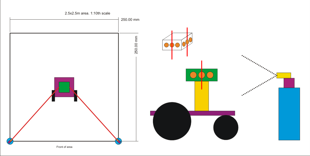
Concept
In the figure above, the outer 2.5m area is the bounds of where the robot is allowed to go. The system will not have to track outside this area. The big purple square is the robotic base I'm trying to track, there are two black wheels either side of it. Now focus your attention to the circles on the bottom left and bottom right of the 2.5m area. The purple squares at 45d are servo motors. The gold squares mounted on top of the servos are line lasers (with the lines set vertically).
Now focus your attention to the diagram to the right of the square area, you can see a side on view of the robot base. The yellow block on the robot is simply a wooden spacer. The green box on top of that is a "cube" of circuit boards, with 3 LDRs/Phototransistors/Photodiodes on each side (denoted by orange circles). (See figure above the side on robot view for a 3D representation). To the right of the side on view of the robot is the "beacon/laser scanner". The blue denotes a wooden block, purple denotes servo, gold denotes line laser.
Step 1 - Laser tracking LDRs
Step number one is this. When the system first turns on, the servo (and thus the laser) scans throughout it's range. When the middle LDR on the robot detects the laser, it sends a message over an RF link to the beacon. The laser should be focused on the centre LDR. (as the diagrams denote).
The second laser will do the same, although will be focusing it's laser on a different side of the "LDR cube". At this point in time the system knows the position of each beacon, along with the angle from each beacon to the robot. It will then bilaterate the position of the robot. This is not particularly difficult - but here comes my question:
When the robot base starts moving, the laser will move off the middle LDR onto one of the outer LDRs (either the one to left or right). Upon doing this the robot will send a message over the RF link to the beacon, telling it to move in the corresponding direction to get teh laser back on the centre LDR. The make or break point of this system is this: How fast does the robot move, and can the lasers keep up?
I'm wanting the robot to move 0.5m-1m / second. That equates to 0.5mm-1mm / millisecond. The LDRs I'm wanting to use have a size of ~8mm^2. That means there's a distance of 12mm from the centre of the middle LDR to either outside edge (where it looses detection). That means, in perfect conditions, you'd have ~8ms between the time that the robot starts moving at 1m/s, and when the laser moves off the edge LDR. Thus, the loop between the laser hitting the outer LDR, sending the signal to the beacon, the beacon processing that and moving has to be under 8ms (at the very most). For reference I'm currently using the nRF24L01+ tranciever modules, which had a response time of <2ms when I tested them (in unoptimized conditions).
Here's what I'm asking: do you think that this system will be fast enough, reliable, and accurate enough to do what I want? My major concerns are the LDRs, the ones which I was planning on buying had a response time of ~40ms, which is much too slow. Would photodiodes be better? What type would I buy? Is the RF system fast enough? Is there an easier way of doing this?
Requirements:
- Has to be built for under $50 (although I have parts I can use here already)
- All parts have to be shipped within a few days (preferably gotten within Australia)
- Has to track to ~10-15cm accuracy, over a 2.5m^2 area.
- Has to be simple enough for me to understand and build")
Parts I already have access to:
- Plenty of MCUs (Props, BS2s, Arduinos, XMOS boards, etc)
- I can easily get LDRs from the local electronics store
- I own 1 line laser, I can aquire a line laser from Little Bird electronics within a week.
- A variety of servos suitable for the task
- Enough tranceivers to make the system work
Thanks for your time and consideration!
John
Perhaps it's the holy grail of robotics - or perhaps not. Either way, I'm needing to design a quick & dirty (also cheap) 2D localization system, that's accurate to ~10-15cm over a 2.5m * 2.5m area.
Enter Figure 1:
Concept
In the figure above, the outer 2.5m area is the bounds of where the robot is allowed to go. The system will not have to track outside this area. The big purple square is the robotic base I'm trying to track, there are two black wheels either side of it. Now focus your attention to the circles on the bottom left and bottom right of the 2.5m area. The purple squares at 45d are servo motors. The gold squares mounted on top of the servos are line lasers (with the lines set vertically).
Now focus your attention to the diagram to the right of the square area, you can see a side on view of the robot base. The yellow block on the robot is simply a wooden spacer. The green box on top of that is a "cube" of circuit boards, with 3 LDRs/Phototransistors/Photodiodes on each side (denoted by orange circles). (See figure above the side on robot view for a 3D representation). To the right of the side on view of the robot is the "beacon/laser scanner". The blue denotes a wooden block, purple denotes servo, gold denotes line laser.
Step 1 - Laser tracking LDRs
Step number one is this. When the system first turns on, the servo (and thus the laser) scans throughout it's range. When the middle LDR on the robot detects the laser, it sends a message over an RF link to the beacon. The laser should be focused on the centre LDR. (as the diagrams denote).
The second laser will do the same, although will be focusing it's laser on a different side of the "LDR cube". At this point in time the system knows the position of each beacon, along with the angle from each beacon to the robot. It will then bilaterate the position of the robot. This is not particularly difficult - but here comes my question:
When the robot base starts moving, the laser will move off the middle LDR onto one of the outer LDRs (either the one to left or right). Upon doing this the robot will send a message over the RF link to the beacon, telling it to move in the corresponding direction to get teh laser back on the centre LDR. The make or break point of this system is this: How fast does the robot move, and can the lasers keep up?
I'm wanting the robot to move 0.5m-1m / second. That equates to 0.5mm-1mm / millisecond. The LDRs I'm wanting to use have a size of ~8mm^2. That means there's a distance of 12mm from the centre of the middle LDR to either outside edge (where it looses detection). That means, in perfect conditions, you'd have ~8ms between the time that the robot starts moving at 1m/s, and when the laser moves off the edge LDR. Thus, the loop between the laser hitting the outer LDR, sending the signal to the beacon, the beacon processing that and moving has to be under 8ms (at the very most). For reference I'm currently using the nRF24L01+ tranciever modules, which had a response time of <2ms when I tested them (in unoptimized conditions).
Here's what I'm asking: do you think that this system will be fast enough, reliable, and accurate enough to do what I want? My major concerns are the LDRs, the ones which I was planning on buying had a response time of ~40ms, which is much too slow. Would photodiodes be better? What type would I buy? Is the RF system fast enough? Is there an easier way of doing this?
Requirements:
- Has to be built for under $50 (although I have parts I can use here already)
- All parts have to be shipped within a few days (preferably gotten within Australia)
- Has to track to ~10-15cm accuracy, over a 2.5m^2 area.
- Has to be simple enough for me to understand and build
Parts I already have access to:
- Plenty of MCUs (Props, BS2s, Arduinos, XMOS boards, etc)
- I can easily get LDRs from the local electronics store
- I own 1 line laser, I can aquire a line laser from Little Bird electronics within a week.
- A variety of servos suitable for the task
- Enough tranceivers to make the system work
Thanks for your time and consideration!
John
Comments
LDRs are slower than photodiodes/phototransistors for sure. Worse yet, they are most sensitive to yellow/green light, not red. Green lasers would help.
I'm a fan of the Hamamatsu sensor, which uses IR or a red laser. I learned much from Philo:
http://www.philohome.com/sensors/lasersensor.htm
http://nxt-unroller.blogspot.com/2012/10/laser-sensor-for-nxt.html
Two of my projects using lasers, that sensor and retroreflectors:
Laser-guided & targeting vehicle: https://www.youtube.com/watch?v=dZTfIyrRne0
Laser tracker: https://www.youtube.com/watch?v=5IvkHokhZsQ Two of those could act as you have described, but speed is an issue. Not sure about tracking 1m/sec. A BS1 version at https://www.youtube.com/watch?v=E7WKzGYqlwQ Also shows 2 lasers tracking the same reflector.
Your robot turns, yes? That is, it translated and rotates, changing its orientation within the 2.5m square?
Thanks, I'm about to go out - I'll check them out in depth when I get back. I also doublechecked the speed, you're right - I made a mistake. I'm looking for ~33cm (0.3m) / sec.
http://forums.parallax.com/showthread.php/161097-Thoughts-on-Prop-suitability-for-something-like-this...
Duane, would this thermopile sensor help your IR tracking idea?
I am not sure if you are aware, but these cheap 5mW, 5v line lasers from ebay throw out a really nice sharp red (650nm) line. Of course, using the prop it is really easy to modulate the laser at 38kHz, or any frequency of your choosing.
http://www.ebay.com.au/itm/Red-Line-Laser-Module-Focus-Adjustable-Laser-Head-5V-Industrial-Grade-5mW-650nm-/400781449348?pt=LH_DefaultDomain_15&hash=item5d506f9884
I have found that the normal beam or pulse 38kHz IR receiver modules are not effective for red lasers, so I have had to make my own beam receiver.
This is not trivial, because you need a bandpass filter amplifier. However, I found the Maxim application note circuit below works very well with the red laser at 10kHz;
There are IR line lasers available, but they are relatively expensive. The advantage is that the IR line laser should be easily received using existing 38kHz IR receiver modules.
For now I prefer to use the red line laser because I can see what is going on (not with my eye, but using a white screen).
The thermopile is sensitive to different range of IR than the IR used by the Wiimote. People "glow" in the far IR but not in the near IR.
I remember back in the days of IR photography people often thought IR film picked up the heat of plants and people. IR photography done with film cameras could see IR from heat but the item would have to be almost "red hot" in order for it to glow "IR hot". I once took a picture of my stove top while it was just a bit too cool to glow red and sure enough it was glowing in the near infrared. Near IR is more like a color we can't see than heat.
I often think it's too bad IR covers such a large chunk of the spectrum. IR LEDs are not putting out the same frequencies seen by thermal imagers.
My idea with the Wiimote camera would be to calculate the position of the robot in a similar way the Wii calculates the position of the Wiimote. Instead of having the LEDs stationary as done with the Wii, the camera would be stationary and the IR LEDs mobile (on the robot). I personally think this would be much easier than trying to aim lasers at a target.
it seems you would have to light a bonfire (sort of burning robot) on the robot to use a thermopile.
Not a problem tracking my bot. https://www.youtube.com/watch?v=fuXMh1_-6Ag