

New to Propeller Board; Questions regarding simple LED exercise
 AHT357
Posts: 1
AHT357
Posts: 1
Hi all,
I was looking for a little help with a simple problem, if you please.
I'm new to using this propeller board, and was going through the following I/O exercise to learn how to use it:
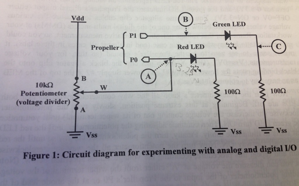
The idea is to measure a variable voltage with Pin 0, and apply it to a digital state of either 0 or 1, while Pin 1 has to match the state of Pin 0. I'm sure I got the resistor values right, and the LED's are forward biased.
It uses this code (It uses a method called PST_Driver I didn't include, but I'm pretty sure is not the problem):
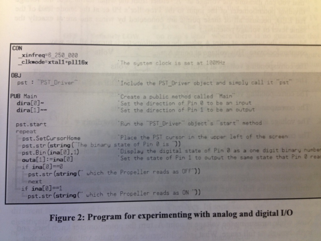
I get the code to work, the "The binary state of Pin 0 is....which.....etc", which switches from 0 to 1 at about 1.46 V, which I know to be correct.
However, I cannot get the green LED, connected to Pin 1, to turn on at all. I thought the point of that Pin was that it doesn't get connected to power, and that the Propeller board supplies it a "HIGH" state, and therefore voltage, when Pin 0 reaches 1.46? Would the board "know" that I'm using the 3.3 V power source for Pin 0, and supply that to Pin 1 when it's supposed to be at a HIGH state from the code being executed?
Am I also correct in assuming that when the potentiometer is turned all the way counterclockwise, pin 0 will experience the full 10K ohms, be practically tied to ground, and the Red LED will be off? That's what I have happen, and I get the Red LED to brighten up once the resistance between the wiper and top goes down from turning it clockwise. But apparently I'm supposed to be getting voltage values around 3 V for both point A and B when the potentiometer is turned fully counterclockwise?
Any help I could get with this is greatly appreciated.
I was looking for a little help with a simple problem, if you please.
I'm new to using this propeller board, and was going through the following I/O exercise to learn how to use it:
The idea is to measure a variable voltage with Pin 0, and apply it to a digital state of either 0 or 1, while Pin 1 has to match the state of Pin 0. I'm sure I got the resistor values right, and the LED's are forward biased.
It uses this code (It uses a method called PST_Driver I didn't include, but I'm pretty sure is not the problem):
I get the code to work, the "The binary state of Pin 0 is....which.....etc", which switches from 0 to 1 at about 1.46 V, which I know to be correct.
However, I cannot get the green LED, connected to Pin 1, to turn on at all. I thought the point of that Pin was that it doesn't get connected to power, and that the Propeller board supplies it a "HIGH" state, and therefore voltage, when Pin 0 reaches 1.46? Would the board "know" that I'm using the 3.3 V power source for Pin 0, and supply that to Pin 1 when it's supposed to be at a HIGH state from the code being executed?
Am I also correct in assuming that when the potentiometer is turned all the way counterclockwise, pin 0 will experience the full 10K ohms, be practically tied to ground, and the Red LED will be off? That's what I have happen, and I get the Red LED to brighten up once the resistance between the wiper and top goes down from turning it clockwise. But apparently I'm supposed to be getting voltage values around 3 V for both point A and B when the potentiometer is turned fully counterclockwise?
Any help I could get with this is greatly appreciated.
Comments
The actual input threashold for the Propeller is about 1.65v (3.3 / 2) -- you'll probably see something much closer to this if you separate the pot from the LEDs -- as in this example.
'' =================================================================================================
''
''   File....... threshold_test.spin
''   Purpose....
''   Author.....
''   E-mail.....
''   Started....
''   Updated....
''
'' =================================================================================================


con { timing }

  _clkmode = xtal1 + pll16x
  _xinfreq = 6_250_000                                           ' use 6.25MHz crystal

  CLK_FREQ = (_clkmode >> 6) * _xinfreq                          ' system freq as a constant
  MS_001   = CLK_FREQ / 1_000                                    ' ticks in 1ms
  US_001   = CLK_FREQ / 1_000_000                                ' ticks in 1us


con { io pins }

  RX1   = 31                                                     ' programming / terminal
  TX1   = 30

  SDA   = 29                                                     ' eeprom / i2c
  SCL   = 28

  LED_G =  2
  LED_R =  1
  POT   =  0


con { pst formatting }

   #1, HOME, GOTOXY, #8, BKSP, TAB, LF, CLREOL, CLRDN, CR
  #14, GOTOX, GOTOY, CLS


obj

  term : "fullduplexserial"                                      ' serial io for pst


var


pub main

  setup

  repeat
    term.tx(HOME)
    term.str(string("The state of the POT pin is: "))
    term.tx(ina[POT] + "0")                                      ' display input as digit, 0 or 1
    term.tx(CR)
    if (ina[POT] == 0)
      high(LED_R)
      low(LED_G)
      term.str(string("...which the Propeller reads as off/low"))
    else
      low(LED_R)
      high(LED_G)
      term.str(string("...which the Propeller reads as on/high"))
    pause(25)


pub setup

'' Setup IO and objects for application

  term.start(RX1, TX1, %0000, 115_200)                           ' start serial for terminal


con

  { ------------- }
  {  B A S I C S  }
  { ------------- }


pub pause(ms) | t

'' Delay program in milliseconds

  if (ms < 1)                                                    ' delay must be > 0
    return
  else
    t := cnt - 1776                                              ' sync with system counter
    repeat ms                                                    ' run delay
      waitcnt(t += MS_001)


pub high(pin)

'' Makes pin output and high

  outa[pin] := 1
  dira[pin] := 1


pub low(pin)

'' Makes pin output and low

  outa[pin] := 0
  dira[pin] := 1


pub toggle(pin)

'' Toggles pin state

  !outa[pin]
  dira[pin] := 1


pub input(pin)

'' Makes pin input and returns current state

  dira[pin] := 0

  return ina[pin]
Another subtle "gotcha" is that there seems to be no delay on sending characters to the display -- you can easily overrun the PST buffer doing this. In my version I added a 25ms delay at the end of the loop.
Welcome to the Propeller. It's really fun. Most of my coding is artistic in nature and you can see some of my projects on this Pinterest page:
-- https://www.pinterest.com/jonmcphalen/techno-art/
Notice that most of it has to do with LEDs; we do lots of crazy cool things with them in Hollywood.
I don't understand this concern. Every serial driver I've seen waits for room in the tx buffer if it's full. Only the rx buffer can be overrun.
At least this my understanding.