

homemade controller for a top secret project under development.
 SONIC the Hedgehog
Posts: 321
SONIC the Hedgehog
Posts: 321
its been awhile since ive posted, but ive got a top seret hardware masterpiece in the making! So here are a few photos and a video showing functionality will be coming soon!
!![P01-17-10_03-20[1].jpg](https://forums.parallax.com/uploads/attachments/66065/87845.jpg)
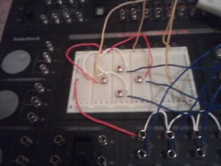
![P01-17-10_03-20[2].jpg](https://forums.parallax.com/uploads/attachments/66065/87846.jpg)
!
Comments
Clearly you are trying to emulate the game Sonic on a propeller!
And don't laugh. Some of this has already been done.
The display is tricky - 320x224 with a 512 color palette. Up until recently I would have said no, as that is too many colors in the palette for the TV and VGA drivers. But with the ILI9325 touchscreen 320x240 and a palette of 64k colors, this is quite possible.
Searching 68000 and propeller on google throws up some intriguing links.
my prop chip is in a box with a controller made of push buttons with a 74hc166 is 8 bit parallel in serial out so it works just like the NES controller
but you can lay out your buttons as you please
I couldn't tell from your pictures if you've got pull-up or pull-down resistors on your buttons.
Here's a little circuit that is commonally used.
*************************************************
    Push Button Schematic
*************************************************
                 3.3V
                          button
                   10KΩ   ─┻─
  Prop Pin  ─────┻────────┘ └─┐
                               
*************************************************
There are lots of different ways of reading push button inputs but the schematic above is about as simple as it gets.
I was thinking about resistor values to use, but ended up leaving them out because I'm using +3v, so I figured that would be fine, and its working okay, except I've got wires everywhere, so some buttons get randomly sensitive.
(don't ask me how I know this!)
They would be randomly sensitive because you have no pullups! Duane's circuit solves the problem.
I'm curious how you have these buttons wired if you're not using pull-up or pull-down resistors.
You really need them.
Me too.....
Basically there is a push button switch in between a prop pin and a supply of +3v.
Add a 10K resistor from the Prop pin to ground (always connected no matter the button state) for each button. You wont have to change your code and the button will be much more reliable.
Pull up vs Pull down. You can choose either. Back in the olden days the way 74xx TTL logic worked, a pullup used less current than a pull down resistor. So pull ups became a convention. With modern chips this does not matter.
With a pull up, the resting state of the pin is "High" and the pushed state is "Low" so that might need a software inversion. So that might be an argument in favor of a pull down, where resting is "Low".
It does not really matter in the end. What you don't want is a floating pin, picking up stray RF from your local radio station and randomly flipping high and low.
I initial suggested pull-up resistors since they seem to be the norm. Now I know why, thanks. I suggested the pull-downs after Sonic told us how his circuit was wired. I figured with the pull-down resistors Sonic wouldn't have to modify his code.
In other words, I agree with you.
Added the resistors like you two suggested, I played TRON light cycles with some code I modified by OBC! Thanks OBC, and Dr. Acula, and Duane!
8 pins per player with direct buttons 16 pins for 2 players 3 for TV DAC one for audio 2 for eeprom and most of the ram boards might take 4 to what 10 pins?
so we are already up to 24 to 32 pins and well thats all your pins
i just want to clarify the GENY had a D pad and a mode and A B C buttons.
the NES had D pad select start and A and B buttons
point its the same a 4 position D pad and 4 buttons just different names on the buttons
the case has an fold up lcd on it, and on my SD card i have lots of the games like load runner defender and dodgey kong modded to my layout.
i recommend you save pins and use some discrete logic chips to shift in data from your buttons you would reduce your foot print down from 8 pins per player to 4 pins for 2 players my home made controller looks noting like a nes controller with just a d pan on one side and 4 buttons on the other side.
I'm just trying to be helpful, and trust me this is easier then it sound. i can post a circuit schematic if you like.
And the object I have used can be found in the obex... here!
http://obex.parallax.com/objects/616/
Once you can use button presses to control the logic in your program you can look for ways of decreasing the pin count of your button pads.