

LED Touch Sensor
 Steve Joblin
Posts: 784
Steve Joblin
Posts: 784
Just saw this via Make.com... looks pretty cool!
LED Touch Sensor
The Physics
Light Emitting Diodes (LEDs) have a natural capacitance, and that capacitance and/or impedance is dependent on the light incident on the diode. (Clearly I need to read up on my device physics).· By reverse biasing the diode, we charge the capacitor. By turning the high leg when charging to an input, and holding the other leg at ground, we source current from the device. Since the RC time changes as a function of ambient light, by choosing a time to poll after the previous hi to input transition, we check to see if the state of the input is high or low. This high/low is our LED switch.
What you need
A micro-controller with ms resolution and at least 2 I/Os, and an LED.
Steps
·
You’ll need to play with that number based on ambient light and LED properties, so it’s handy to make that adjustable during run time. If you find that the LED discharges too quickly, you can either increase the charge time in step 2 OR add a small resistor (100 to 470 ohms) in series on either side of the LED (remember t is proportial to R*C). The resistor in series will also limit the current (which is good for the LED) but it will also limit the intensity when the light is on.
Basic Stamp Code
Here’s a quick demo to get you going with a basic stamp, using pins 1 and 2
‘ {$STAMP BS2}
‘ {$PBASIC 2.5}
pausetime VAR WORD
trigger VAR WORD
polltime VAR WORD
pausetime = 1 ‘Set time between steps
polltime = 10 ‘Set time to poll after swtiching to input
Main:
‘Light ON
HIGH 1
LOW 2
PAUSE pausetime
‘Charge
LOW 1
HIGH 2
PAUSE 1
‘Input
LOW 1
INPUT 2
PAUSE polltime
IF IN1 = 0 THEN
trigger = 1
DEBUG “On”
ELSE
DEBUG “Off”
ENDIF
GOTO Main
Post Edited (Steve Joblin) : 6/9/2007 1:01:47 PM GMT
LED Touch Sensor
The Physics
Light Emitting Diodes (LEDs) have a natural capacitance, and that capacitance and/or impedance is dependent on the light incident on the diode. (Clearly I need to read up on my device physics).· By reverse biasing the diode, we charge the capacitor. By turning the high leg when charging to an input, and holding the other leg at ground, we source current from the device. Since the RC time changes as a function of ambient light, by choosing a time to poll after the previous hi to input transition, we check to see if the state of the input is high or low. This high/low is our LED switch.
What you need
A micro-controller with ms resolution and at least 2 I/Os, and an LED.
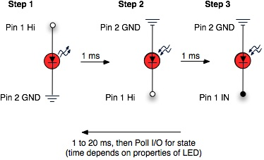
Steps
- Turn the LED On for 1 ms
- Reverse Bias the LED for 1 MS
- Turn the Hi in the last step to an input, and wait for 1 - 20 ms.
- Repeat steps 1 - 3
·
You’ll need to play with that number based on ambient light and LED properties, so it’s handy to make that adjustable during run time. If you find that the LED discharges too quickly, you can either increase the charge time in step 2 OR add a small resistor (100 to 470 ohms) in series on either side of the LED (remember t is proportial to R*C). The resistor in series will also limit the current (which is good for the LED) but it will also limit the intensity when the light is on.
Basic Stamp Code
Here’s a quick demo to get you going with a basic stamp, using pins 1 and 2
‘ {$STAMP BS2}
‘ {$PBASIC 2.5}
pausetime VAR WORD
trigger VAR WORD
polltime VAR WORD
pausetime = 1 ‘Set time between steps
polltime = 10 ‘Set time to poll after swtiching to input
Main:
‘Light ON
HIGH 1
LOW 2
PAUSE pausetime
‘Charge
LOW 1
HIGH 2
PAUSE 1
‘Input
LOW 1
INPUT 2
PAUSE polltime
IF IN1 = 0 THEN
trigger = 1
DEBUG “On”
ELSE
DEBUG “Off”
ENDIF
GOTO Main
Post Edited (Steve Joblin) : 6/9/2007 1:01:47 PM GMT
bmp
248K
Comments
pause polltime
Thanks
Sid
▔▔▔▔▔▔▔▔▔▔▔▔▔▔▔▔▔▔▔▔▔▔▔▔
Sid Weaver
Do you have a Stamp Tester yet?
http://hometown.aol.com/newzed/index.html
·
And there have been guys putting patents in to use the display (LEDs) of a device as a means of communication, such as data sending, flashing, etc...
Look here:
http://mrl.nyu.edu/~jhan/ledtouch/index.html
I have set up reading a line of LEDs as a sensor (and output at the same time!)
I plan to write an app note about it in the near future.
With the stamp I used RCTime to read levels...
Ryan
▔▔▔▔▔▔▔▔▔▔▔▔▔▔▔▔▔▔▔▔▔▔▔▔
Ryan Clarke
Parallax Tech Support
RClarke@Parallax.com
Apparently color choice can make a difference in response to ambient light conditions.· And there is more...
▔▔▔▔▔▔▔▔▔▔▔▔▔▔▔▔▔▔▔▔▔▔▔▔
"When all think alike, no one is thinking very much.' - Walter Lippmann (1889-1974)
······································································ Warm regards,····· G. Herzog [noparse][[/noparse]·黃鶴 ]·in Taiwan
Ryan
▔▔▔▔▔▔▔▔▔▔▔▔▔▔▔▔▔▔▔▔▔▔▔▔
Ryan Clarke
Parallax Tech Support
RClarke@Parallax.com
thanks
also, ryan, any news on the app note? that would be really helfpul.
▔▔▔▔▔▔▔▔▔▔▔▔▔▔▔▔▔▔▔▔▔▔▔▔
D Faust
▔▔▔▔▔▔▔▔▔▔▔▔▔▔▔▔▔▔▔▔▔▔▔▔
D Faust
▔▔▔▔▔▔▔▔▔▔▔▔▔▔▔▔▔▔▔▔▔▔▔▔
D Faust
Post Edited (D Faust) : 6/9/2007 7:21:58 PM GMT
I noticed that none other than Parallax's own Chris Savage had edited my post... don't know why he did, but his name was showing on the bottom of my posting!
From the link above:
"Rule of thumb #2: LEDs will only detect light of wavelength shorter than the wavelength of light that the LED would emit if it was put in a circuit that forward biased the LED.
For example, a red LED will detect light emitted by a yellow LED and a yellow LED will detect light emitted by a green LED but a green LED will not detect light emitted by a red or yellow LED. All three LEDs will detect "white" light or light from a blue LED. White light contains a blue light component which can be detected by the green LED. Recall that visible light wavelengths can be listed from longest wavelength to shortest wavelength as Red, Orange, Yellow, Green, Blue, Indigo, Violet (remember the mnemonic "Roy G. Biv"). Violet is the shortest wavelength light with the most energetic photons and red has the longest wavelength light with the least energetic photons of all of the visible colors of light."
Mike
▔▔▔▔▔▔▔▔▔▔▔▔▔▔▔▔▔▔▔▔▔▔▔▔
D Faust
▔▔▔▔▔▔▔▔▔▔▔▔▔▔▔▔▔▔▔▔▔▔▔▔
D Faust
·
The attached jpg is a screenshot from my BitScope showing the voltage after the resistor just before it goes into P7 on the Propeller.· The slope downwards is the capacitance of the LED discharging when I turn the output of the cathode to an input.· The problem is that I don't see the slope change at all when I am covering the LED versus being in full bright light.· Also I have changed LEDs and only see a very very slight change in capacitance, but again no change if I am covering it or it is out in the open.
·
Any suggestions?· Maybe I need a different type of LED.· I am using·the diffused lens variety; perhaps water clear lense is better?· The circuit has the Anode of the LED attached to P6 and the cathode of the LED is attached to a resistor and then the resistor is attached to P7.· Can't be any easier, right?
·
Wait a minute - it appears the slope downwards is not due to the LED capacitance.· I just pulled my green LED out to verify one more time that a yellow and·a red LED give the same results and I see the waveform does not change.· The waveform bare·adjust without a completed circuit.· Hmm....does that mean the internal capacitance of the pin is causing the slope?
·
OK - so my problem is that I don't see a slope from the capacitance of an LED.· Any suggestions?·
·--edit: uploaded correct code
▔▔▔▔▔▔▔▔▔▔▔▔▔▔▔▔▔▔▔▔▔▔▔▔
Timothy D. Swieter
tdswieter.com
One little spark is all it takes for an idea to explode
Post Edited (Timothy D. Swieter) : 6/16/2007 12:39:27 PM GMT
It's interesting, in a cutey-pie way I suppose,·the little projects and all, but the rubber on this jalopy simply doesn't meet the road -- the demonstrations are always (surprised?) in a dark room.· As you're discovering, using an LED as a substitute for a switch just isn't living in the real world.
Sid
▔▔▔▔▔▔▔▔▔▔▔▔▔▔▔▔▔▔▔▔▔▔▔▔
Yesterday is history, tomorrow is a mystery, and today is a gift.
That is why they call it the present.
Don't have VGA?
Newzed@aol.com
·
▔▔▔▔▔▔▔▔▔▔▔▔▔▔▔▔▔▔▔▔▔▔▔▔
Timothy D. Swieter
tdswieter.com
One little spark is all it takes for an idea to explode
▔▔▔▔▔▔▔▔▔▔▔▔▔▔▔▔▔▔▔▔▔▔▔▔
Timothy D. Swieter
tdswieter.com
One little spark is all it takes for an idea to explode
Sid
▔▔▔▔▔▔▔▔▔▔▔▔▔▔▔▔▔▔▔▔▔▔▔▔
Yesterday is history, tomorrow is a mystery, and today is a gift.
That is why they call it the present.
Don't have VGA?
Newzed@aol.com
Sid
▔▔▔▔▔▔▔▔▔▔▔▔▔▔▔▔▔▔▔▔▔▔▔▔
Yesterday is history, tomorrow is a mystery, and today is a gift.
That is why they call it the present.
Don't have VGA?
Newzed@aol.com
·
Later I will dig out some blue LEDs and try them.
Also it appears to work best in a room with light.· The light in the room versus a close finger provides a greater difference in the capacitance than a dark room.
▔▔▔▔▔▔▔▔▔▔▔▔▔▔▔▔▔▔▔▔▔▔▔▔
Timothy D. Swieter
tdswieter.com
One little spark is all it takes for an idea to explode
Sid
▔▔▔▔▔▔▔▔▔▔▔▔▔▔▔▔▔▔▔▔▔▔▔▔
Yesterday is history, tomorrow is a mystery, and today is a gift.
That is why they call it the present.
Don't have VGA?
Newzed@aol.com
·
I have [noparse][[/noparse]crudely] modified your code to:
a) Drive four 3mm red LEDs, using one cog per LED (all the spare pins on the demo board)
b) Use a 'SetPoint' threshold that is the average of the Calc_Values from all four LEDs (helping to deal with ambient lighting conditions)
c) Create some 'bargraphs' (i.e., rows of '#' characters) on a VGA screen
d) Reduce the 'ms' delay
From 25m I could detect the output of a 3mW laser driven by 4.2V - getting the beam to line up with one LED was the difficult part. At 25m I ran out of garden...
Red laser + green LEDs were no good.
Photodiodes + IR were no good.
Photodiodes + red laser were no good.
It does seem very sensitive, but not (yet) sensitive enough to send data, mainly because of the cycling of the LED. The great things is that I haven't used any resistors, capacitors or Op-amps - I have a digital brain and these fiddly things are too like 'shades of grey' for me!
Cheers
Hugh
▔▔▔▔▔▔▔▔▔▔▔▔▔▔▔▔▔▔▔▔▔▔▔▔
Hugh - the thinking woman's Geoffrey Pyke.
I too found the green ones are the most sensitive to ambient light .
when I was developing the PhotoPhone ,I got over 500 Feet with a green DPSS laser .
From what I found its s LOS ( line of sight) issue .
Peter KG6LSE
▔▔▔▔▔▔▔▔▔▔▔▔▔▔▔▔▔▔▔▔▔▔▔▔
"Carpe Ducktum" "seize the tape!!"
peterthethinker.com/tesla/Venom/Venom.html
Never underestimate the bandwidth of a station wagon full of tapes hurtling down the highway. —Tanenbaum, Andrew S.
LOL
Humanoido
Peter KG6LSE
▔▔▔▔▔▔▔▔▔▔▔▔▔▔▔▔▔▔▔▔▔▔▔▔
"Carpe Ducktum" "seize the tape!!"
peterthethinker.com/tesla/Venom/Venom.html
Never underestimate the bandwidth of a station wagon full of tapes hurtling down the highway. —Tanenbaum, Andrew S.
LOL
The time cycle for each reading can be made consistent (and speedier) in two ways -- tuning the RC portion of the circuit for faster discharge times, and deciding on an upper threshold of the RC time measurement. In my own projects, I nearly always include an LED-as-light-sensor, as the same LED can be used for a hearbeat indicator, etc (presuming I have two free pins, that is).
citeseerx.ist.psu.edu/viewdoc/download?doi=10.1.1.69.1570&rep=rep1&type=pdf
▔▔▔▔▔▔▔▔▔▔▔▔▔▔▔▔▔▔▔▔▔▔▔▔
When the going gets weird, the weird turn pro. -- HST
create bitmap data tool: 1uffakind.com/robots/povBitMapBuilder.php
resistor ladder tool: 1uffakind.com/robots/resistorLadder.php
convert images to ascii art: 1uffakind.com/apptoys/convtoascii/