

Crane load balancer (was: Universal Motor Driver board, parallel connection?)
 ManAtWork
Posts: 2,199
ManAtWork
Posts: 2,199
I have a project where I need to move a counterweight on a crane to keep the load balanced. The motor is battery powered and is rated 500W @24V. So the rated 20A of the Universal motor driver board should be just enough. But I like to have a little headroom...
Is it possible to connect two of the 4 phases in parallel to get higher current output? The on/off delay times of the seperate half-bridges might not be exactly matched but this shouldn't cause an issue as long as the dead time (break before make) is greater than the longest turn off delay. The MOSFET with the longest turn-off delay or the shortest turn-on time has to take all the current for a very short time but as long as the current is below the rated pulsed current it shouldn't blow up, I think.
The maximum continuous supply current is rated 20A. I think that is the current capacity of the terminals and copper traces. But a motor current >20A should occur only when the motor voltage is well below the supply voltage. So the supply current should always stay below 20A.
Comments
Theoretically there's no problem, powerFETs will happily parallel up.
Of note, those powerFETs are 130 A rated but package derated to 85 A and further to 54 A at 100 degC. I'm assuming the DFN5060 package is good at dissipating heat into the PCB. Maybe there is a case for the PCB track current capacity not being sufficient for running continuously above 20 amps.
Huh, actually, the spec says 20 amps for "all phases". I suspect that means added together rather than 20 each. In other words the board isn't meant to draw more than 20 amps from the supply in total. So the limit isn't with the transistors but rather with the supply side ... ah, and the current sense resistor will be part of that. There's only one for the whole board.
PS: Reference - https://www.parallax.com/product/universal-motor-driver-p2-add-on-board/
Ah OK, I see. The terminals are rated for 32A and the 0.005 Ohm shunt resistor can take 3W which is around 24.5A. So I put a 25A fuse in the supply line and limit the current to 50A peak and 25A continous in software and with the two outputs connected in parallel. I have a Rev A board which might be sensitive to negative voltage spikes at the gate drivers. I think there were some damaged boards and Chip modified the drivers for Rev B for that reason. I hope it doesn't blow up and I can at least do some experiments. If the customer is happy with the solution I have to make my own board, anyway.
Exactly that.
I'd have thought that f you parallel two (or three) breakouts in a way that each phase parallels with another board, W-W, X-X, Y-Y, Z,Z (ie. not just on the same board W-X, Y-Z) and supply VIN to each direct to source, you should be good for 20A per phase, assuming 2 are active at once. Also assuming you use the exact same Rev breakouts, as the switching timing is slightly different between the Revs. Would that be fun to code offsets for")
I haven't tried to look at any other details of revA vs revB but that sense resistor has been changed from 5 mR to 3 mR, making for a more robust handling of >20 amps. Throwing a 2 mR resistor in there instead will probably be the best way to allow even more current.
EDIT: Oh, revB also has a x50 gain op-amp on the sense resistor. Hmm, so the revA is gonna be a downer to measure if it is reduced even further.
EDIT2: You know what, I'm not convinced that x50 is the right setting. It hits 3.0 Volts at 20 Amps! There's no allowance for peak current beyond.
Yes, the rev A board is probably not the best choice. But I don't really need precise current/torque control. Limiting the current for protection is enough so a smart pin in comperator mode should probably work. If I can at least demonstrate basic function I'll get the budget to make my own board. I'll put a 25A hall current sensor, there, which has it's built-in amplifier and around 30mV/A sensitivity. That's equal to 3mR and a gain of 10.
Good approach. Those little surface mount resistors have a habit of fusing at high current.
I finally decided to use a off-the shelf Cytron motor controller instead of doing modifications to the Parallax motor driver board or designing my own board. The Cytron board is for DC motors only and is rated 30A continous and 80A peak. It has internal overcurrent protection so I can't burn things with software bugs. It costs about the same as the Parallax board and is easily setup using DIP switches. It takes 1..2ms RC servo pulses which are easy to generate with only one smart pin.
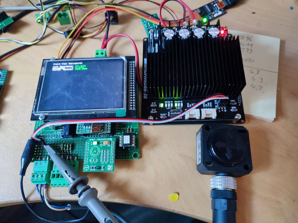
The inclination angle is measured by an analogue sensor from DIS sensors.
Today we ran the first full scale test. We had some small issues with overshot and oscillations but after reducing P and I gain and increasing D it works quite well.

Of course, the whole thing is a pendulum and there is a strong tendency for resonance oscillation. With a real crane where the hook is quite heavy it even becomes a double pendulum. I thought about adding anti-resonance filtering but soon gave up. The length of the cable and the varying load make both resonance frequencies variable so the filter should have auto-tuning and everything gets really complicated. I think, a strong D-gain should provide enough anti-phase stimulus and hopefully enough damping.
I've had good luck with those, too. very flexible
That's where those inverse kinematics algorithms get used. Basically build a behavioural feed-forward model instead of filtering the feed-back. Not that I've ever used such myself.
Yes, if this was a rocket-science project with unlimited budget I'd probably build a behavioural model. I can't measure the cable length directly but I have a barometric pressure sensor on-board (see picture in post #8) so I could adapt to changing height above the ground while the load is lifted.
But I think it's much easier to tell the worker to put his hand on the load until it stops swinging.
It's all about controlling the motor ;-)