

Smart Mode Synchronous Serial Transmission in continuous mode
 jrullan
Posts: 178
jrullan
Posts: 178
Hi,
I'm trying to modify the ILI9341 driver from the OBEX, which uses smart pins to drive the SPI communications, to see if I can get it to send all pixels in an image using continuous mode instead of it's default start/stop mode.
The driver implements two write commands to send values to the SPI pins:
write - which uses 8bit start/stop mode
write16data - which uses 16bit start/stop mode
write
                shl     data, #24 wc                    ' prep byte to write (msb first), bit8->C
                call    #selectLCD                      ' prepare LCD smart pins
                rev     data                            ' reverse bits in data (31..0 -> 0..31)
                wxpin   #$27,PIN_SDA                    ' 8 bits, start/stop mode
                wypin   data,PIN_SDA
                drvl    PIN_SDA                         ' enable TX smart pin
        _ret_   wypin   #16,PIN_CLK                     ' start CLK sequence

write16data     shl     data, #16                       ' prep word to write (msb first)
                modc    _set wc
                call    #selectLCD                      ' prepare LCD smart pins
                rev     data
                wxpin   #$2F,PIN_SDA                    ' 16 bits, start/stop mode
                wypin   data,PIN_SDA
                drvl    PIN_SDA
        _ret_   wypin   #32,PIN_CLK
I can send an image using this function:
send_image_data
                'Setup FIFO read of image data
                rdfast #0, data1

                'Send command to ILI9341
                mov     data, #LCD_RAM_WRITE            ' Send LCD_RAM_WRITE command to ILI9341
                call    #writecmd

                'Send pixels to ILI9341
.next_pixel     rfword  data                            ' Reads a pixel from imagePtr into data
                call    #write16data                    ' Send pixel data to ILI9341
                djnz    pixelno,#.next_pixel            ' Decrement pixelno and if not zero loop for next word (pixel data)
                jmp     #done
However, that function adds all the SPI overhead per pixel. It occurred to me that I could do something like this to make sure it sends pixel data continuously:
send_image_fast
                'Setup FIFO read of image data
                rdfast #0, data1

                'Send command to ILI9341
                mov     data, #LCD_RAM_WRITE            ' Send LCD_RAM_WRITE command to ILI9341
                call    #writecmd

                modc    _set wc                         ' sets up transmission of data (c=1) not command (c=0)
                call    #selectLCD

''----------------------------------------------------------------------
                rfword  data                            ' Reads Initial pixel data
                shl     data, #16                       ' prep word to write (msb first)
                rev     data

                wxpin   #$0F, PIN_SDA                   ' configure continuous mode, 16 bits
                drvl    PIN_SDA                         ' start transmission for 16 bits (32 transitions = 16 clock cycles)
                wypin   #32, PIN_CLK

.next_data      djz     pixelno,#.end_of_tx             ' Decrement pixelno and if zero end, else get next data

                rfword  data                            ' Reads NEXT pixel data
                shl     data, #16                       ' prep word to write (msb first)
                rev     data

.bufnotempty    testp   PIN_SDA, wz                     ' wait until pin is ready for new data (Z = IN)
        if_nz   jmp     #.bufnotempty
                wypin   data, PIN_SDA                   ' Move new data to buffer if buffer empty
                jmp     #.next_data

.end_of_tx      testp   PIN_CLK wz                      ' IN=1 if smart pin ready
        if_nz   jmp     #.end_of_tx                     ' wait until last CLK sequence finished
                jmp     #done
''----------------------------------------------------------------------
where the wxpin #$0F, PIN_SDA value should set up 16 bit continuous mode.
The theory is that this function keeps setting the buffer with new pixel data every time the IN flag is set indicating that the buffer is empty and ready for more data and the pixels are sent continuously until the last pixel finishes transmitting.
This function currently does not work and I'm wondering if there is something I don't understand or that I am overlooking. Any help or pointers are appreciated.
(I only included here the relevant parts of the driver as it is a big driver)
Comments
In continuous mode, preload the shifter before raising DIR.
EDIT: As in starting word is the exception. After that IN performs as buffer empty as usual.
@evanh thanks for the feedback.
Would the following modifications take care of it?:
                ...
                wxpin   #$0F, PIN_SDA                   ' configure continuous mode, 16 bits

                dirl    PIN_SDA     '<---- DIR=0
                wypin   data, PIN_SDA   '<---- Preload data goes directly to shifter

                drvl    PIN_SDA                         ' start transmission for 16 bits (32 transitions = 16 clock cycles)
                wypin   #32, PIN_CLK
                ...
I completely missed that in the Smart Pins document by Jon Titus.
However with the above modification it still isn't working.
Yep, that looks appropriate. I'll need to look harder for something else ...
It might be where the first bit lands. In continuous mode the first bit is presented ahead of the first clock and the second bit is shifted out upon the first clock. I'm unsure if that's what you'll get in start-stop mode. It might have a low ahead of first clock then shift out the first bit upon the first clock.
PS: Continuous mode's early bit phase can be an advantage in countering the notable staging latency in the Prop2's I/O.
Is that something that happens during every WYPIN or just on the preloading one?
It's the first clock-data phase relationship, after a CS cycle, where it gets set but that then follows on indefinitely to all bits.
We're basically talking about the SPI Clock-Mode: CPOL and CPHA. Dig out an Oscilloscope or Logic Analyser to confirm actual behaviour of your setup so as to then make correction.
PS: You've got a clock divider of sysclock/64. That's plenty large enough to not have to worry about the I/O staging latencies. One less headache.
Oh well. Thank you for your suggestions. I don't have either so I wont be able to troubleshoot that far.
This is clearly above my knowledge and abilities, so I guess for now I'll just use the existing commands.
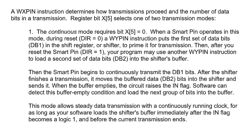
It seems they are the same clock-data phase relationship. I've just done a quick test using both modes for comparison and got virtually identical results. (top is start-stop mode, bottom is continuous mode)
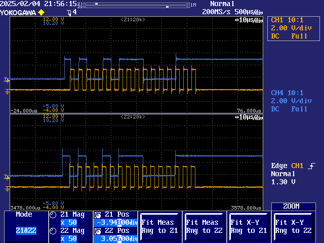
At first blush it looks like the data is transitioning on the rising clock edge, and that is exactly what the smartpin is trying to do, which is generally a bad sign, but upon closer inspection the staging latencies lags the data transitions a good distance behind the clock edges:
So, this test is also not showing up any real problems.
Thank you @evanh for that. I suppose then it's an implementation problem.
So I noted in your example code you are sending only one word at the time in continuous mode. I don't think it matters that much at least for the checks you performed. However I would like to understand better what is the correct workflow for continuous mode. As I understand it right now:
4.1. Wait until IN is 1
4.2. Load next data into Y
This is my interpretation of the documentation so far for this mode. Maybe there is some nuance to how it should be done that I'm missing.
Re-reading the smart pins supplemental documentation...
I makes me wonder if the transmission could be ending before the next data is written in the Y register. I don't know how strict it is in terms of writing immediately after IN=1. My current implementation reads and process the data from the FIFO before writing it to Y:
send_fast 'Setup FIFO read of image data rdfast #0, data1 'Send command to ILI9341 mov data, #LCD_RAM_WRITE ' Send LCD_RAM_WRITE command to ILI9341 call #writecmd 'Reset smart pins for data transmission modc _set wc call #selectLCD ' prepare LCD smart pins 'Setup 16bit contiuous mode wxpin #$F,PIN_SDA ' 16 bits, continuous mode 'Preload data (directly into shifter) dirl PIN_SDA call #.write16fast dirh PIN_SDA 'Fill buffer with next data call #.write16fast 'Start transmission wypin #32,PIN_CLK 'Loop for all pixel data .bufnotempty testp PIN_SDA, wz ' wait until pin is ready for new data (IN = 1) if_nz jmp #.bufnotempty djz pixelno,#done ' Decrement pixelno and if zero end, else get next data call #.write16fast jmp #.bufnotempty .write16fast rfword data shl data, #16 ' prep word to write (msb first) rev data _ret_ wypin data,PIN_SDAAfter running some estimates, even if I can make it work, I don't think the gains are significant in my use case to pursuit this approach any longer. There is still a lot of overhead processing per pixel to properly prepare the data for transmission. Even running the SPI clock at 10MHz as it is now, the additional instructions add little for a full screen of pixels compared to the time it takes to transmit all the bits. I guess a better use case would be if the data to be sent is already msb first aligned and packed in 32bits.
So you're saying the tx rate is already almost as fast as the software can feed it?
I've solved it, btw. Buffer empty doesn't come true unless the buffer had something in it first. So the buffer empty check has to wait until after first topping up the buffer.
5.1. Wait until IN is 1 (buffer empty)
5.2. Load next data into Y (buffer)
PS: I've changed to sysclock/8 on this example. That's about as fast as you want to go in cmode=0. cmode=3 can get to sysclock/4 with a little trickery.
Oh, another pitfall to steer clear of is testing IN too quickly after a WYPIN. IN needs a spacer instruction after a WYPIN before it becomes valid.
Eg: This works:
                wypin   pa, #PIN_SDA    ' refill buffer
                nop
.wait
                testp   #PIN_SDA   wc    ' check for buffer empty
        if_nc   jmp     #.wait
But this doesn't work:
wypin pa, #PIN_SDA ' refill buffer .wait testp #PIN_SDA wc ' check for buffer empty if_nc jmp #.waitThank you so much @evanh I will test this during the weekend.