

P2 Evaluation Board - Accessory Set 64006-ES
 VonSzarvas
Posts: 3,639
VonSzarvas
Posts: 3,639
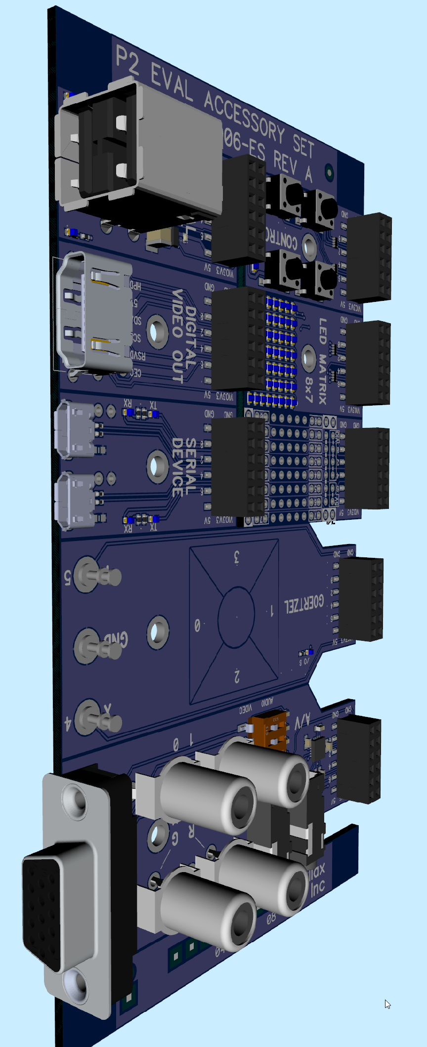
Here's some images of the Parallax P2-ES Accessory Set.
Sharing what I know so far...
These will be sold as a set of 8 PCBs, with part number 64006-ES.
64006-ES(a) - Control (4 Buttons, 4 LEDs)
64006-ES(b) - Serial Host (Twin type-A stacked socket)
64006-ES(c) - 8x7 LED Matrix
64006-ES(d) - DVO (Digital Video Out)
64006-ES(e) - Mini-Prototype board
64006-ES(f) - Serial Device (Two MicroUSB sockets)
64006-ES(g) - Goertzel experimenter with 3 Scope Probe posts (X, Y, GND)
64006-ES(h) - AV (Headphone, Microphone, Composite Video, Audio-to-RCA 4-band, VGA)
The PCB's are sized such that you can connect all eight boards to the eight P2-EVAL header positions at once.
These are planned to run through manufacturing next week, so an official announcement could appear with pricing & ordering details soon!
There will be a larger protoboard (64005-ES) sold separately, which I'll post in a moment to a new thread.

1446 x 2020 - 393K
864 x 2119 - 344K
Comments
I take it those headers are bottom-entry. Are the holes in the middle of the boards for spacer posts?
Thank you, and also YES and YES.
The mount holes are all positioned the same distance from the edge furthest from the pass-through SMT header, are GND connected, and are good for M3 hardware.
(With the exception of the mini-prototype board- somehow the hole didn't quite fit
I really like this idea
re:64006-ES(b) - Serial Host (Twin type-A stacked socket)
I assume that is USB sockets also (type-A stacked socket).
YES.
This breakout has two sockets stacked on-top each other, and could accept USB style mouse and keyboard, for example.
They all have a common theme. Power(3.3/5), Ground, Clock, Data, D/C, CS.
That way I only need to select the voltage and plug the Gyro, Accelerometer, GPS, Wi-Fi Module, RTC board, Flash memory, and OLED device in and I'm ready to code.
And when the ESP code is ready I can remote load my P2.
Mike
j
You could do that with either the mini or full-size protoboard. Solder on a row of sockets, and plug in your existing accessories.
If you don't, it might be hard for users to find a cable, with the correct wiring.
I think that bit means that the 4 RCA jacks can be video or audio. So no special cable.
The headphone and mic jacks look to be just "normal" jacks, and not what you are thinking of.
My question is related the "Audio-to 4-band RCA Mini-Connector" that I believe carries; "Left Sound Out", "Right Sound Out" and "Composite Video Out"?
But it doesn't say that in this thread anywhere except your post.
His post says "Audio-to-RCA 4-band". Looking at the images and his post, I don't think there is a "mini connector" that is both composite video and audio.
So there are two of those jack sockets on the AV board.
One is wired for a mono microphone, tip signal and body ground.
One is wired for stereo sound out from a small on-board amp. Tip left, Middle Right, Body ground.
I think these are both really standard audio / headphone cables, like Roy said. Those sockets do not include the composite video signal, which I figure is what you thought.
Incidentally, I totally agree that having an AV cable available to buy with the Badge would be a good thing. I will mention this again.
That mini-jack connector you mentioned on the Propeller Activity Board is for audio and video (4 pole 3.5mm jack)
The mini-jack connectors on this AV breakout are for audio only, and are split between audio out and audio in. So there is no sharing of cables. Everything is single cable, in the most simple form possible.
For video, you would hook into the RCA sockets, not the mini-jack sockets.
Thank you for the clarification of connectors on the "AV breakout" board.
Mike
The pins from the P2-ES board come up through the bottom of these boards into the connectors you see.
Mike
Mike
Correct.
This type of connector is often called "Pass Through" or "Bottom Entry".
They are handy for automated manufacturing, as these types of connector can be placed by machine and soldered through the oven.
And these will work with the acrylic enclosure we are all using?
Edit: if not, can header extension be provided in the kit?
One observation was that due to the rounded edges on the acrylic case vs the 90 degree PCB corners, a little sand-paper might be recommended to clean the PCB corners of the breakouts (on the SMT header edge), for a perfect and beautiful fit.
That might not still be a "thing", but that's what I heard about it earlier in the process. It didn't seem like a big amount, and I do recall seeing 3D models (from Rich) of the case with breakouts installed at some point over December. So he certainly took the breakouts into account.
2 layers, yes. (Phew!)
On corner clearances, Goertzel board is tightest with ~65 mil clearance. Rest are ~100 mil.
Might be just a 10-20 mil shave needed to hug the acrylic curve - that's assuming the acrylic curve wasn't enlarged before the cases were made.
@W9GFO will know the final details on that. Either way, plenty of space.
Overall- I think Rich did a splendid job, considering he had no actual boards to work from! Darn amazing result.
These will look really nice together with the EVAL board and Rich's case.
Cool! Thanks for explaining this. I have never seen a connector like that.
HyperRAM is certainly an omission, tho that would need dual headers.
There is also OctaRAM...
Possible on a single connector, would be these QuadSPI PSRAMs
Mouser show stock of IS62WVS5128GBLL-45NLI, which is 4MB, 45MHz Static SRAM, higher price, smaller, but no refresh imposed caveats.
I would suggest max-out a single board with 3? x SO8's and 3? x chipselects.... all QuadSPI connected to cover RAM/PSRAM/FLASH/Other variant memory