

Project: Praying Mantis
 Team_Mantis
Posts: 3
Team_Mantis
Posts: 3
Welcome to project Praying Mantis! We are a groups of Sacramento City College students, sponsored by the Electronics Student Association on campus, who plan to develop and bring to life an autonomous 4-legged walker robot powered by parallax parts and components. Our design inspiration is the mighty praying mantis; with its four graceful legs and its tall and strong upper body. We have been working on it for the past 4 months or so now as part of an advanced student lab class and its come a long way in that time. My name is Chance, username fancychance, and my partner is Chris, user name currbot. We hope to enter this robot into the state fair this upcoming summer
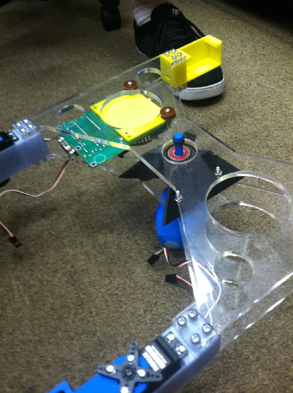
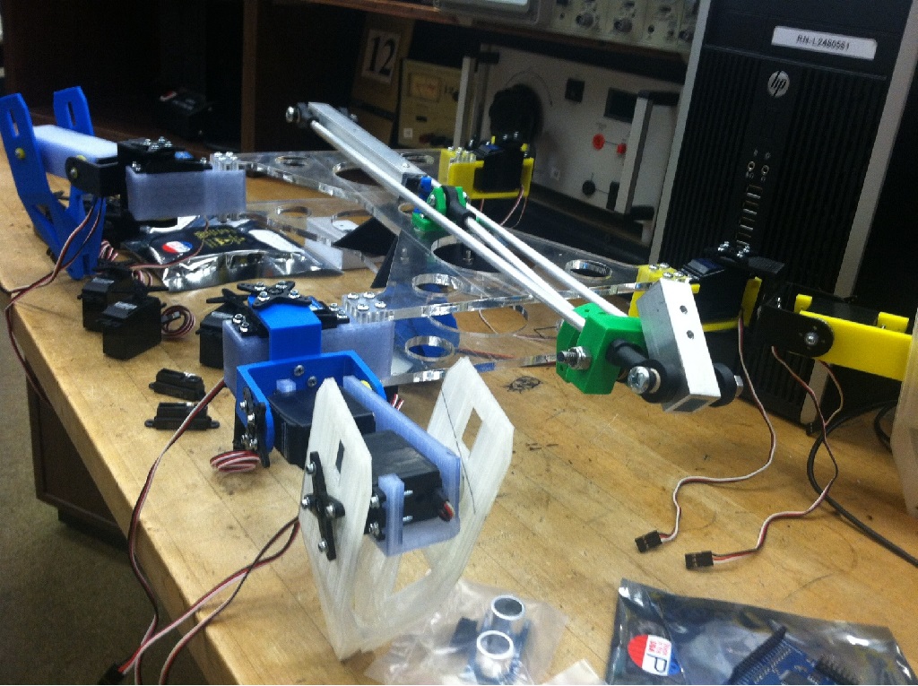
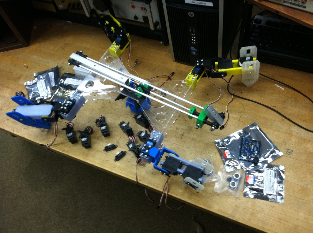
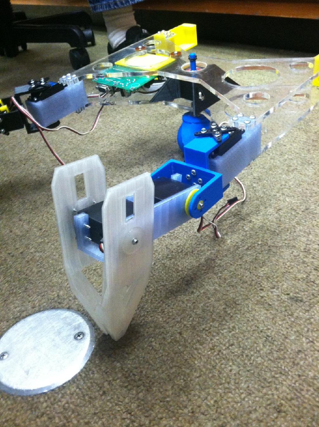
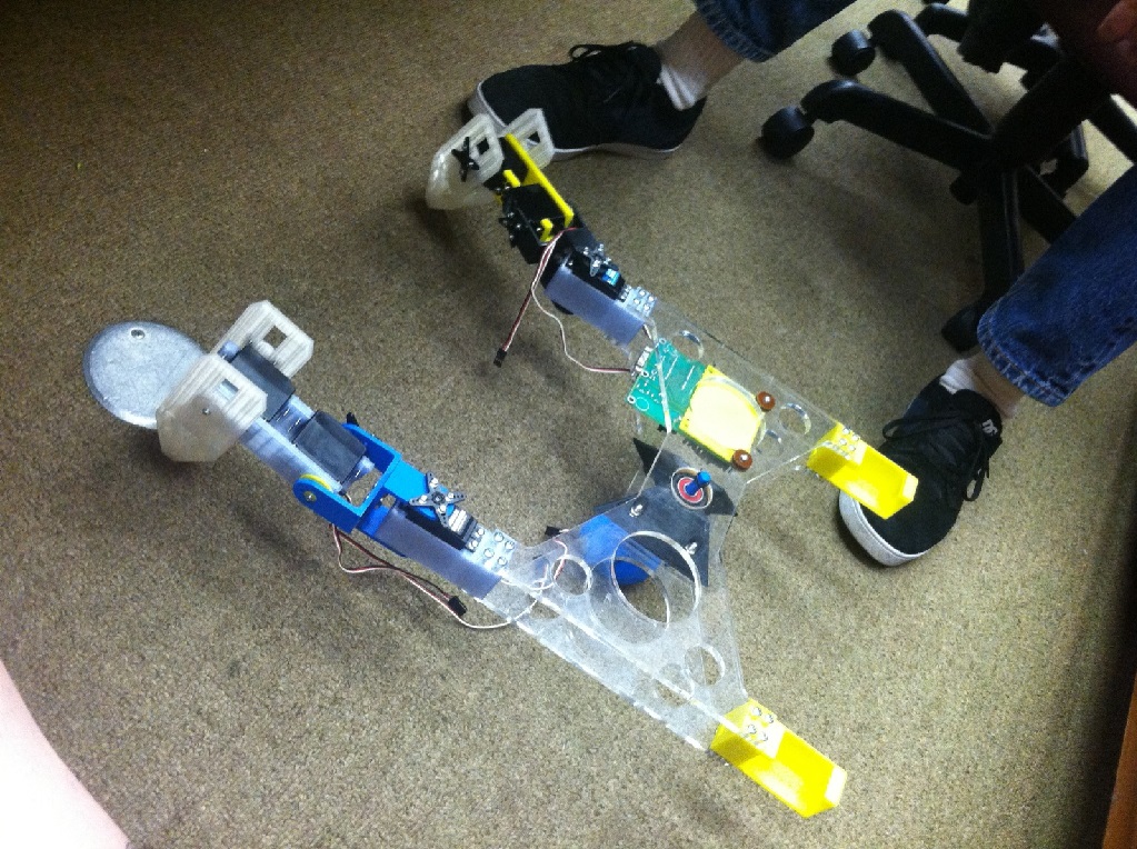
As of right now, the mantis is made uses 12 continuous rotational servos (3 per leg) for movement. The body is made up of 2 Plexiglas plates that were shaped with a laser cutter on campus; they lay parallel next to each other, so the boards and sensors can sit safety between the plates. The legs themselves are made of a very lightweight plastic which was created on an amazing 3D printer. the servos are a bit old, so new higher torque servos are eventually going to replace all the servos that we have equipped now, and we've decided on using the propeller board as the main brain, in addition to using an adafruit 16 channel servo driver shield. The unit as a whole is a bit heavy, so instead of having the servos carry that heavy load all over the place, Chris developed a really neat 360 degree rotating ball the body can sit on and still move around.
We just received a propeller board, courtesy of Parallax, that will run the entire system. Our team is well trained with the basic stamp, but hopefully it wont be hard to familiarize with the new propeller board. Same with the Adafruit servo shield; this will be our first time driving this many servos from one board, so hopefully no catastrophes will occur!
We will be posting much more photos as the Mantis keeps growing, we also have no problem with feedback and suggestions about the Robot! Never quit building!

1022 x 1370 - 533K

1024 x 765 - 305K
1022 x 762 - 306K
1023 x 1369 - 573K
1023 x 764 - 370K
Comments
I think it will be easier to control your robot using normal servos rather than continuous rotation servos.
There's some discussion about different types of servos in my hexapod thread. I show the insides of a few different kinds of servos in post #59. I still think HobbyKings HXT-12K servos are a good value.
The Propeller is a great microcontroller for controlling servos. Without any extra hardware, the Prop can drive 32 servos.
I think Adafruit makes some great stuff but I don't really see a need for the servo shield. Instead of sending all the servo positions to the servo board, just use one cog to control all 12-servos. IMO, it will be easier to drive the servos directly from the Propeller than sending the commands to the other board.
Good luck on your project and I look forward to future updates.
If you're cash-strapped and need servo donations, hit up companies like Pololu, Sparkfun, or even direct to HiTec. It's good mojo, press, and PR for them to help you out, just as Parallax did with their Propeller.
Don't be afraid to ask, you have nothing to lose.
There are lots of ways to connect servos to the Propeller. In the 32 servo demo, I use a breadboard to add power to the servos while connecting the signal to the Propeller.
I designed some small PCBs to use with my Halloween Hex project. They're working pretty well. I just attached the zipped up gerber files to the PCB to this post. You can submit the zip file to OSH Park and have some boards made for your robot. Earlier in the Halloween Hex thread I show another PCB for use with servos made from some perf board. I generally connect the servo's signal wires directly to the Propeller's I/O pins without a resistor or level shifter.
Getting power to lots of servos can be a challenge. Most servos can't take more than 6V so you either need a battery pack with a voltage between 4.8V and 6V or you need to regulate the voltage with a buck converter (voltage regulator). The little $2 or $3 regulators won't cut it for use with lots of servos. You'll probably need to spend around $12 for a good regulator (if you need one). I think there are links to regulator options in the Halloween Hex thread.
I don't see how continuous rotation servos will work? You'll need some sort of position feedback so the Propeller can know when to stop moving a servo.
Your camera arm looks cool but it also looks really heavy. You might want to start out testing the robot without the arm attached. Once the robot is walking, you can see if the robot can support the weight of the arm (I'm afraid it won't be able to support the weight of the arm).