

MOSFET to switch between USB 5V and Battery (FT232RL,TLV755,SI2323DS
 doggiedoc
Posts: 2,254
doggiedoc
Posts: 2,254
I've got a few areas I'm a little unsure of; if anyone want's to offer any suggestions:
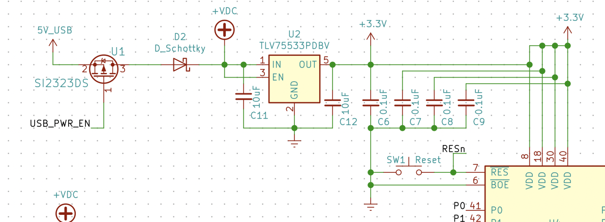
In the schematic below:
1) I am trying to replicate how the QuickStart board can use power or Vin - I'm an a little vague on the MOSFET and how it works. Does this look right? Here is the LINK for data sheet for the one I've chosen.
The full schematic is attached below. I have more questions but trying to stay focused.
Any help is appreciated!
Paul
Comments
so to turn it ON the gate needs to be sinked to ground, that is what the ftdi chip does after enumeration.
Your mosfet have a low -vgs requirements and very low on resistance so will work great.
The Schottky diode is so reverse current can not flow backwards up in to the usb system if you power the board in other ways.
The do make usb power switch ic's that does both these functions plus more, if someone was trying to get lower bom count.
https://www.mouser.com/ProductDetail/Diodes-Incorporated/AP22811BW5-7?qs=sGAEpiMZZMuCmTIBzycWfOZ4FJeyTsh9kQXXT64cY9f59Mg3E/A39g==
But This one is designed for discharging any residue of the output voltage when either no external output resistance or load resistance is present at the output.
Pinout Table:
30 /USB_PWR_EN (Labeled /UPE) Allow Power Sourcing from the USB Port
Pin Function List:
/USB_PWR_EN — USB power enable pin, inverted. Pulled to USB 5 V supply. Internally pulled
low after successful USB power negotiation. Drive low to force the USB power input to drive the
QuickStart power supply. Drive high with 6 VDC to disable power sourcing from the USB
connector. Rev B and later boards also internally pull low /USB_PWR_EN low upon detecting a
USB charger. Rev A boards must have /USB_PWR_EN externally driven low to power from a USB
charger.
I am not sure of the function of the D1 Schottky diode since applying 6V at USB_PWR_EN to disable USB power actually would allow 5.25V (the diode on the Quickstart BOM shows a 0.75V drop) to be present on the other side of the Schottky which is 5V USB. I must be missing something there. David Carrier did the Quickstart design, maybe you can email Parallax support and ask them to have him provide a detailed explanation.
I looked at the MIC2025. I saw that in the J-Tagulator. Decided to stick with it this way for now but will try it later.
I've attached the "final rough draft" of my schematic. I'm feeling better about it now.
Thanks again guys!
Paul
When you want to use this schematic to make a layout you should not use the same power symbols at both sides of FB1. KiCAD will connect these two in the netlist.
Do you really want R40 to be only 12Ohm. That will result in a very bright LED.
You are right. I probably don't want the full 25mA to those. That was copied from D5-D32 which I want to be bright. D35 is only the power indicator so I'll calculate a new on for that. That goes for D3 and D4 as well. Thanks!
Paul