Engine RPM Signal from Primary Ignition Coil
I am trying to get a Engine RPM signal from the primary coil on my 98' Ninja 500r.
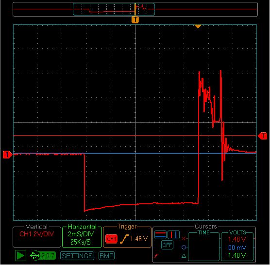
The first scope pattern is of the primary coil building up current and then collapsing it (the peak voltage) to create current in the secondary coil to then fire the spark plug. This one is with out the BS2 connected between the resistors.
My plan is to monitor the voltage drop across the 10k resistor. I would use the pulsin command to measure the time in state 0. With the first scope pattern and a on/off threshold on the BS2 of 1.5v, This would measure the time between coil firing peaks and then be converted to engine rpm. As engine speed increases, the pattern frequency increases and the pulsin duration would decrease proportionally.
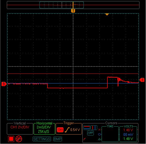
The second scope pattern is with the BS2 pin 0 connected between the resistors.
When the BS2 is connected, my voltages are pulled down by the input pin. Rendering my calibrations useless.
I simulated the same resistor circuit with a constant voltage, a 9v battery in place of the primary coil, and got these voltage readings:
9.6v across the battery
3.1v dropped across 10k w/o BS2 connected
1.48v dropped across 10k w/ BS2 connected
I also tried removing the 10k resistor with the BS2 connected and it had no affect on the voltage readings.
Why is the BS2 pulling my voltages down?
Isn't it supposed to be able to read voltages with a high internal impedance that won't affect the circuit operation? Like a DVOM.
How can I get a engine rpm signal in another way?
Thanks for your time and help.
-Aaron


Comments
A more logical place to take a reading would be from the switched side of the coil primary to ground. You will see a large positive excursion significantly above +12V when the switch opens, so you'll definitely need additional input protection for the Stamp. A network consisting of a couple series resistors and a zener diode to ground on the downstream side of each one would be an absolute minimum. An MOV in parallel with the first zener would provide an extra margin of protection.
-Phil
▔▔▔▔▔▔▔▔▔▔▔▔▔▔▔▔▔▔▔▔▔▔▔▔
Think Inside the box first and if that doesn't work..
Re-arrange what's inside the box then...
Think outside the BOX!
You take some 22 or 24 gauge wire and wrap to try 100 turns on a hard plastic sleeve
that you put over the secondary wire
on one side of the wire you put a diode to clip off any negative voltage
use a small ceramic cap to level the spike a bit and a 1k resistor to limit current flow
you may have to add or remove turns on the coil to get the 4-5 volt peak after the forward
voltage drop of the rectifier diode
you could also put a 5.1 volt 1/2 watt zener diode in reverse bias to absorb any higher voltages
just to be on the safe side or slightly paranoid.
Since you have a scope that should be really easy to do
edit:
you will need a resistor in paralell to the small capacitor
The bigger the cap the more noise will be reduced and the peak may also level out
but you will need a smaller ohm'd resistor to bleed off the stored electricity in the cap
also another positive effect is it has no connection to the electrical system
and a caution dont wind a thousand turns on the coil or the voltages can get to high
use a 1" wide piece of plastic and keep the windings 1/2" wide max
then tape the wire around the tube to prevent the wire from going all over.
if you are going to use it long term you also want to tape the plastic to the secondary
wire to prevent the tube from moving around as the tube moves around
the voltages may change a bit depending on a number of factors.
Post Edited (Skeil) : 11/14/2007 8:18:06 PM GMT
It sounds like you are doing the same thing I'm trying. I need to also use a signal from my ignition to determine engine RPM for my SX chip.
Does your ignition system use points or not? If it doesn't it should have a hall effect sensor in the distributor - or where ever it picks up the timing - the output of this sensor should be logic level. I have the factory manual from Ford for my truck here and I will try that here to see if it is a signal I can use or not. According to the manual here it is a logic level output that goes to the computer. Ford calls it a PIP - Profile Ignition Pick-up
I know your engine is much different than a V-8 truck engine, but perhaps both have this in common.
I was about to ask the same question you did, and reading yours got me thinking, so I looked in the manual and came across some hopefully useful info, but have not tried it myself yet.
Maybe this helps,
Alex
▔▔▔▔▔▔▔▔▔▔▔▔▔▔▔▔▔▔▔▔▔▔▔▔
When I go, I want to go peacefully in my sleep, like my grandfather, not screaming and yelling like the people who were in the car with him.