BS2 Universal Guitar Tuner Project Version 2.0
The Background Story
Since I first posted this Project I have been working with JohnBF to allow this circuits to work with a wide base of microphones as well as electric guitars - the following circuits is the result of a series trials and reinventions.
All timings are BS2 specific but can be modified - I've included my spreadsheet In case any of you want to modify it.
The Circuit
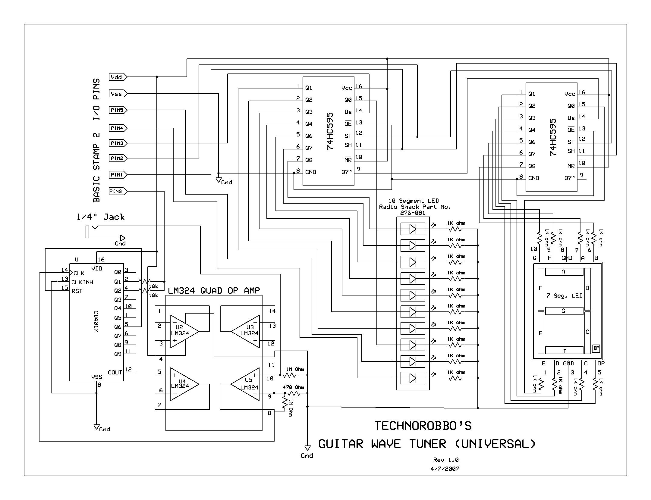
The circuit creates·a super-amplified signal·that "clips" the wave into a square wave- the top and bottom half of 2 waves are summed·and sent to the BS2 for meausring with the pulsin command. To compensate for piezo pickups, a 1 meg resistor was added to ground. The speed of the BS2 worked against us since it was crucial that the wavelength had to be measured as a whole and not 2 parts (high and low).· I solved both those problems by adding a CD4017BE decade counter which summed the top half and bottom half of the wave. I also used the CD4017BE as a frequency divider allowing· the BS2 to measure higher frequencies and lower freq's more accurately.
JohnBF has been testing circuit mod after mod with me and is working on a propeller version using the same front end circuit.
The Software
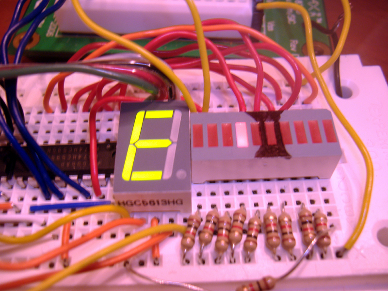
The new code is faster and has excellent noise rejection. The code measures·a wavelength·and displays the·Note and the Tuning Position·on the LEDs'. The LED's Decimal point denotes a Sharp.· (Like any tuner it's best to use 12th fret·Harmonics - the notes have less transients and are more stable.)
The Parts List is a follows.
2 -·74HC595 Shift registers (Parallax)
1 - CD4017BE Decade Counter/Divider
1 - LM324 Quad Op Amp (Radio Shack)
1 -·7 Segment LED Number Block (Parallax)
1 - 10 LED Bar Display (Radio Shack 276-081)
18 - 1k Resistors
2 - 1 Meg Resistor
1·- 470 Ohm Resistor
1 - 1/4 inch Jack
▔▔▔▔▔▔▔▔▔▔▔▔▔▔▔▔▔▔▔▔▔▔▔▔
Have Fun
TR
Post Edited (TechnoRobbo) : 5/6/2007 7:00:38 AM GMT


Comments
Hey, thanks for posting this - I've been wanting to put together a tuner for quite a while. Just happened to have all the parts lying around, so I wired one up on a Parallax Professional Development Board. Unfortunately I can't get it to recognize an incoming signal. I play an acoustic guitar, so I'm using the piezo transducer pickup I use with other tuners. Might it need a stronger or different kind of signal from an electric guitar pickup?
/John
/John
/John
Well, maybe I'll try taking the SX out of its slot but I don't see how that could make a difference.
/John
/John
/John
/John
What could that mean? Oh well, when I show it off I'll just have to say, "Why is that instrument attached? Well, I'm still testing the parameters...".
/John
Now that the front end works, I'm thinking of playing around with more visually interesting ways of displaying the note and pitch, and perhaps switch to a propeller to broaden the possibilities. Should be fun.
Thanks for sticking with this!
/John
With my equipment and setup, the new code is a win-win: faster and seems more accurate. The new circuit is more accurate using a dynamic mic, but it doesn't work at all with my piezo pickup. I'd like to stick with the piezo, so for now I'll keep the old circuit, and use the new code as the basis for exploring display ideas.
By the way, one thing I realized as I experimented is that I really want to be able to display sharp and flat symbols. A serial LCD would be easy, but it maybe not fast enough. If so, I'll try driving a parallel LCD directly. Of course the propeller will drive a small video screen but that's probably overkill. Maybe print sharp and flat symbols on something clear and have LEDs light them.
Looking forward to trying out any more tweaks you come up with!
/John
In the meantime I'm using your April 4 schematic and April 6 code (I'm keeping track!).· I got an LCD display going, along with the LEDs. The LCD display does lag behind the LEDs by just a hair, but it's fast enough to be entirely usable - in fact the LCD makes it usable in a very natural way. If anyone is interested, attached is the code I added for the LCD, and a photo of my test setup.
/John
I've watched what happens more closely with the April 4 schematic, which works quite well, but sometimes (like all tuners) has trouble finding the note. The dynamic mic seems to be slightly better with the lower note strings (4, 5, and 6) and the piezo is slightly better with the higher strings (1, 2, and 3). But either way it already works better than some of the cheaper commercial tuners I have and almost as good as my longstanding favorite, the Boss TU-12 in the photo above. Not bad! Still, I'd be happy try any new ideas you have.
What about software? Kalman filters do a great job cutting through exactly the kind of noise coming in from the pickup. I have a friend in the industry, and he doesn't know any trade secrets, but he thinks Kalman filters, or similar routines are used in the better tuners. He doesn't actually know what Kalman filters are, but he's heard the term. No question a kalman filter requires too much processing power for even the fastest of the BS2s. But it should be possible on a propeller. There's a thread on the propeller forum from some people trying, or hoping someone comes up with a Kalman filter routine for the prop. I'm working on it too, but I have a long way to go.
Or maybe there's something less sophisticated than a Kalman filter, but more robust than averaging five readings. Any thoughts about this?
/John
I have no idea why this tuner works so well with a banjo, and others don't. The banjo notes are mostly within the same range as the guitar (the highest note on the banjo is the fifth string which is a g, two notes above the high e string on the guitar). The banjo has less sustain than an acoustic guitar, but maybe fewer overtones.
I'd be happy to try any more ideas you have but in the meantime I'm also putting together the prop version. I had a little trouble figuring out how to drive an LCD with the prop, but that's solved. The prop should solve several problems. One is that I don't have to worry about the LCD slowing down the note-finding routines since the LCD driver can run in parallel. And for software enhancements there's more than ample variable space, floating point math and all.
/John
▔▔▔▔▔▔▔▔▔▔▔▔▔▔▔▔▔▔▔▔▔▔▔▔
Have Fun
TR
Post Edited (TechnoRobbo) : 5/6/2007 6:50:22 AM GMT
I am trying to suppress the harmonics of the guitar string for this design..
my plan so far is 2 part:
analog agc and comparator circuit looking just below the top rail
then looking for the greatest time that repeats
using software to supress the harmonics
this may involve a different tuner design
I have worked out a design using a standard 32 khz clock crystal
and an external counter
do you think you design can handle the stamp doing SoftWare Supression
or should I start my design in another thread ?
12 bit external counter
Note F T Count
E2 82 Hz 0.01219 3994
A2 110 Hz 0.00909 2978
D3 147 Hz 0.00680 2228
G3 196 Hz 0.00510 1671
B3 247 Hz 0.00404 1323
E4 330 Hz 0.00303 992
32.768kH clock crystal T = .0000030517578125
Ed