

Is the P2 5V tolerant?
 carver
Posts: 1
carver
Posts: 1
in Propeller 2
Is the P2 5V tolerant? Will I be able to interface directly with 5V TTL chips like the 74xx family or with microprocessors like the Z80?
Comments
No. It's a 3.3v device; any signal driving high or low into the P2 should be current limited.
Same rules as the Propeller 1.
Even if the P2 were 5V tolerant meaning that it would then be able to accept 5V signals while operating at 3.3V, it would still only output 3.3V at best to the 5V logic which is below the minimum 0.7Vdd CMOS high theshold. Sure, you could put buffers in there to translate that to 5V but then you wouldn't need a 5V tolerant device.
5V TTL logic is a different matter though since it will accept a minimum of 2.4V (from the P2) as a logic high and typically the Voh (to the P2) would be around 3.4V which could be interfaced direct to the P2 in both directions. Remember, we can have signals up to 3.6V (Vdd+0.3V) in before the CMOS structure starts clamping and this is not problem with TTL since it has an emitter follower + series diode which both end up dropping around 1.6V.
So the P2 has protection diodes like the P1 and 5V signals can be applied through a suitable series resistor?
Yes, we are using 22k series resistor to look at signals that are + / - 12v DC
Virtually all CMOS inputs have "protection diodes" as part of the input structure and it is common practice to use series resistors to limit the current. If you are simply sensing slow signals in the range of a 1kHz of so then that resistor can be quite high, say 100k or even 1M and so therefore will be able handle quite high voltages. Ignoring track inductance etc there will be an RC timing effect on the signal which will limit the useful speed or perhaps the latency might be more important. A 0 to 24V signal through a 100k resistor with around 10pF gate + track capacitance will have an RC time delay of 1us. Remember though that figure is at 63% voltage level from 24V but it is also clamped by the diodes so effectively the signal sees no practical delay and the input current is kept to a low 240uA (-3.6ua). The same circuit with a 1MHz logic signal will not work though.
While 240uA sounds low just remember that this current is not flowing directly to ground though a zener, it is conducting through a diode to Vdd since the clamp voltage is spec'd as >Vdd+0.3V. Ok, no problem so far, but what happens when you have multiple inputs or have too low a resistance and end up having a few milliamps that needs to be clamped? No problem, the load on the supply such as the P2 will handle it. But what happens when the P2 is being reset, and the load is now very light? The input current may cause the supply rail to climb and regulators can't help since they only source current. The abnormal voltage on the supply can cause problems, certainly this was the case with the P1 and it would fail to load serially after a serial reset pulse.
So there are things to watch out for since it's not a free lunch, but the good thing about series resistors is that you can design them in and simply load whatever value you like, be it 100R or 100k. So I make it a practice to always use series resistors on any I/O that is connecting to external signals, and a value of 1k for instance can connect directly to an LED or base of an NPN etc, or as an input. But if the input signal is unplugged or unpowered then the input will float and stray currents can cause the input to see a signal that isn't really there or worse if it is around the switching threshold it can cause both complementary MOSFETs (CMOS) on the inputs to partially conduct and draw excess current as if shorting out the supply rail to ground. So use pull-up or pull-down resistors on the signal side of the series resistor if that could be the case.
BTW, I probably said way more than I really wanted to, but I find that a lot of info out there concentrates solely and simply on "clamp current" and sometimes speed without considering all these other aspects, and yet there are still more.
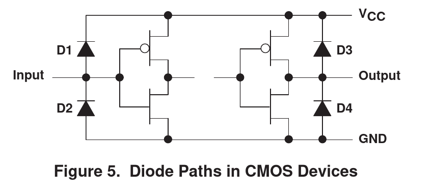
EDIT: CMOS diode structure image:
Those protection diodes come in handy if you want to measure P2's own die temperature. I'm doing it fairly extensively for system identification purposes, i.e. when software running on P2 needs to model the thermal effects on the analog functions, to improve their performance.
@kuba That's a neat trick! How well does it work?
It's a bit hard to say "how well" because I don't particularly care about temperature in engineering units, nor even about it being linear. An observer of what would "nominally" be considered temperature (based on diode models) is taking measurements on a multitude of pins, and that's then used to model thermal gradients across the die (IIRC 1st and 2nd moments in both planar axes), and that's then fed to other empirical models of the DAC resistors, DAC switch mosfets, etc. Those are mostly black-boxes that come from system identification "exercises", but since P2 has lots of cycles available for what I use it in, I can afford to do some hard core system id and modeling in order to pre-compensate the "shortcomings" of its analog circuitry. It works well enough to give me analog peripherals a bit better than they'd otherwise be. I'm still in the exploration stage for those approaches since I'm rather under-educated when it comes to modern system identification.