

P2-based waterfall display for ISM-band radios
 avsa242
Posts: 487
avsa242
Posts: 487
Hi guys,
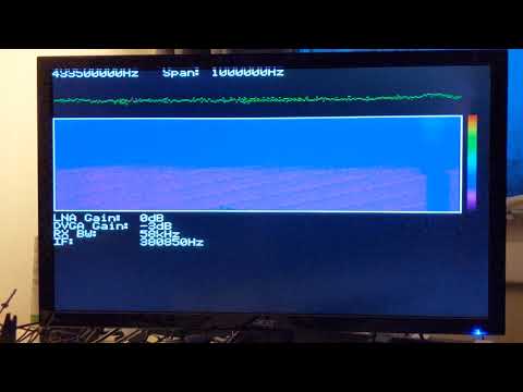
Here is a project I'm working on for the P2 that displays a live spectrogram(-ish) waterfall of ISM-band radio on a 320x200x8bpp VGA display.
If you have a CC1101 module (something like one of these: https://www.amazon.com/SMAKN®-Wireless-Technical-External-Antenna/dp/B00U5TO37W/ref=sr_1_2?dchild=1&keywords=cc1101&qid=1586877604&refinements=p_85:2470955011&rnid=2470954011&rps=1&sr=8-2), you can try it out.
This uses one of those chips to sweep through a frequency band and read the power level/RSSI at each frequency (no FFT is used for the display), and display the power level as a different color (uses a "jet"-like color palette, but also includes a greyscale one).
It's not very sophisticated yet - only a few of the radio's settings can be changed (RX gains, RX bandwidth, IF) and the reference level can be changed. The HID right now is just single-key serial-terminal commands.
The basic requirements are a revB P2, a supported module, and FastSpin to build it.
There are a few variables that can be changed near the top of the Main() method: the base/start frequency, and the initial frequency span setting (span can be changed during runtime)
All of the objects used are from a p2 library I maintain at https://github.com/avsa242/p2-spin-standard-library, but I've packaged everything needed in the zipfile.
Supported transceivers:
CC1101 (315, 433, 868, 915 MHz bands)
CC2500 (2.4GHz)
SX1231 (coverage similar to CC1101)
In the future, I'd like to add:
* Peak hold/reset
* Markers
* Support for other radios (like CC2500, SX1231 (EDIT: Added), SX1276, etc...for other frequency coverage, and to see if any of them perform better than a CC1101)
* Demodulation (e.g., see a signal of interest on the waterfall, add a demodulator for it)
* Save screenshots to SD
* Save demodulated data to SD
* Better interface
* Optimization - it's a bit slow right now
I've posted two videos for those unable to run it:
The first video is of the 433MHz band in my area, a few peoples' weather sensors can be seen transmitting. The second is used pretty heavily by National Grid (the audio in the background isn't from this") - it's from a PC-based radio receiving the same band).
- it's from a PC-based radio receiving the same band).
Note the text cutoff at the top...this is due to my monitor...I couldn't get the timing quite right for it to sync properly.
EDIT 4/28/2020:
- Added thousands separators to the base freq and freq span displays
- Added support for SX1231
- Added support for CC2500
Repository added to github - check here for updates:
https://github.com/avsa242/rf-waterfall-prop2/commits/testing
Cheers
Here is a project I'm working on for the P2 that displays a live spectrogram(-ish) waterfall of ISM-band radio on a 320x200x8bpp VGA display.
If you have a CC1101 module (something like one of these: https://www.amazon.com/SMAKN®-Wireless-Technical-External-Antenna/dp/B00U5TO37W/ref=sr_1_2?dchild=1&keywords=cc1101&qid=1586877604&refinements=p_85:2470955011&rnid=2470954011&rps=1&sr=8-2), you can try it out.
This uses one of those chips to sweep through a frequency band and read the power level/RSSI at each frequency (no FFT is used for the display), and display the power level as a different color (uses a "jet"-like color palette, but also includes a greyscale one).
It's not very sophisticated yet - only a few of the radio's settings can be changed (RX gains, RX bandwidth, IF) and the reference level can be changed. The HID right now is just single-key serial-terminal commands.
The basic requirements are a revB P2, a supported module, and FastSpin to build it.
There are a few variables that can be changed near the top of the Main() method: the base/start frequency, and the initial frequency span setting (span can be changed during runtime)
All of the objects used are from a p2 library I maintain at https://github.com/avsa242/p2-spin-standard-library, but I've packaged everything needed in the zipfile.
Supported transceivers:
CC1101 (315, 433, 868, 915 MHz bands)
CC2500 (2.4GHz)
SX1231 (coverage similar to CC1101)
In the future, I'd like to add:
* Peak hold/reset
* Markers
* Support for other radios (like CC2500, SX1231 (EDIT: Added), SX1276, etc...for other frequency coverage, and to see if any of them perform better than a CC1101)
* Demodulation (e.g., see a signal of interest on the waterfall, add a demodulator for it)
* Save screenshots to SD
* Save demodulated data to SD
* Better interface
* Optimization - it's a bit slow right now
I've posted two videos for those unable to run it:
The first video is of the 433MHz band in my area, a few peoples' weather sensors can be seen transmitting. The second is used pretty heavily by National Grid (the audio in the background isn't from this
Note the text cutoff at the top...this is due to my monitor...I couldn't get the timing quite right for it to sync properly.
EDIT 4/28/2020:
- Added thousands separators to the base freq and freq span displays
- Added support for SX1231
- Added support for CC2500
Repository added to github - check here for updates:
https://github.com/avsa242/rf-waterfall-prop2/commits/testing
Cheers

Comments
I think you just need to add some blank lines at the top of the display and maybe subtract some blank lines from the bottom of the display, in order to get your text downwards a bit.
There are diagonal patterns in the waterfall display. It seems like maybe the initial pixel column is not always starting at the same frequency.
One other thing, it might be nice to add some underscores to numbers, so that 1000000 becomes 1_000_000. Or commas, 1,000,000.
Thanks, I thought the P2 would be perfect for something like this
@pedward, @cgracey
Unfortunately, I think most of the staircasing is due to the whole thing being a little too slow. Signals from around my area that are intermittent and out of my control appear at the same relative frequency every time, but I have just set up a P1 board with another CC1101 transmitting over cable direct to the P2 and it walks a very consistent staircase (in contrast, looking at the same transmission on the PC sdr it's rock solid at the same frequency).
I'm sure it's due to more than one factor (one might be that my SPI engine is running in the same cog as the main cog - I don't have a replacement for it yet. I'd like to take a look at one of the newer engines others have written to see if they might help).
The datasheet also specifies a minimum amount of time to get a robust reading from the power level, although I think this is more for getting accurate absolute measurements; for the purposes of this (right now anyway), I think being able to discern a relative difference should be adequate, though I'll try playing with delays between changing frequencies and reading RSSI...
Yeah the text is a little tough to read as-is