Colorizing the Background of 1-BPP (Monochrome) Bitmap Picture
 JRetSapDoog
Posts: 954
Yesterday, I began to read through the streamer section of the P2 documentation in earnest. It's starting to slowly click into place now, at least for some of the video aspects. Previously, I didn't fully appreciate that there was a one-level buffer for xcont/xzero commands that would allow one to continue to do work in the cog while using the streamer in the background. Although I've read and skim read P2 forum threads over the course of its development, it sure sinks in a lot better (or one's motivation to learn goes up) once one can try code out on hardware. Previously, I was just lightly following what others were doing on the FPGA boards and, later, on the Rev A Eval, But now it's about practice instead of just “book learning.” So, I encourage anyone who's interested in the P2 but hasn't got a board to get one (they should be in stock again soon with Parallax, and Peter's P2D2 board is also coming out right about now).
So, after running code that was modified by rayman to display an 8 bits per pixel bitmap (at a resolution of 640x480) on the Rev B chip, I wanted to modify it to display a 1-bpp image to check my understanding of some of the video modes. At first, all I got was a rapidly flashing image. I had neglected to divide the D/# block count operand by eight (I wasn't sure if that would be done “automagically” when I changed the video mode or not). But after dividing by eight, I had a picture on the monitor.
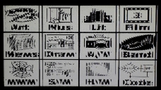
However, the output wasn't quite right (See Picture 1A below). It looked like it had something funky going on every eight pixels or so. So I googled the matter, and lo-and-behold, rayman had described an issue rendering 1-bpp bitmap images a couple of years back. He stated, “Seems the bytes are in the right order, but the bits in each byte have to be reversed to display correctly.” And he provided code to reorder a 1-bpp bitmap such that it could render properly with the streamer. Thanks very much, rayman! Note: It appears that the REV instruction could previously take two operands, whereas it only takes one now; so I slightly altered things to get the code to compile for the actual P2 chip:
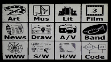
And rayman's fix did the trick. The rendered image now looks like that in Picture 1B below. I realize that that image isn't optimized in terms of contrast and design, but it's good enough to do some experiments with. Apologies for my screen photography; I had the lights off and the white background came out grayish.
By the way, from reading up on the metadata for bitmap pictures (.bmp/.dib) and looking at the actual data for my image using the HxD Hex Editor, it appears that one needs to skip over 54 bytes plus the two color values (four bytes each), for a total of 62 ($3E) bytes, to get to the actual image data. But I don't know if that always works for every 1-bpp bitmap image.
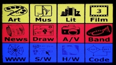
Anyway, emboldened by the progress (thanks to rayman's efforts and sharing), I decided to see if I could colorize the three rows of the original black-and-white image (It has 3 rows x 4 columns). Doing so can be done just before the streamer pumps out the pixels for the visible part of the line. That resulted in the image in Picture 1C below.
Next, I thought that I'd try to change the colors for the right two columns in the image (I decided to leave the left two columns alone since I was just experimenting). Going into this, I wasn't even sure if such recoloring was possible, but it is (which I'm sure comes as no surprise to most of the readers here). The LUT colors are changed by the cog while the streamer is rendering the visible lines. For the result, see Picture 1D below.
I assume that I've done this in a lame way. I'm just using the getct, addct1 and waitct1 instructions, which causes the cog to stall while it waits for the set interval to elaspe. But it was just a proof-of-concept of sorts, and it gets the job done, at least for learning purposes. I presume that it could be written using just getct (or using cycle counting) to avoid the stall in order to have the cog do more work, but at this stage, I'm just pleased to get this far.
Well, for what it's worth, I'll attach the files. Keep in mind that this is hot off the press, and most of the code was written by others. Again, it's just for experimentation. I'll include the bitmap file(s), too. The coloring modifications that I added are written for a system clock frequency of 200 MHz. If you change the frequency, you have to change the timing delays or it will throw off the alignment of the colorization for the columns (and possibly not even produce a valid video signal). I believe that you can set the basepin to a multiple of 4 no matter whether it resolves to port A or port B. However, I've only tested it on multiples of 8. Specifically, I've checked basepins of 0, 8, 16, 24, 32, 40 and 48 (I've not tried a basepin of 56 and don't plan to, as perhaps that would conflict with the boot stuff).
Anyway, I'm really a greenhorn at this (and with working with assembly). And I'll probably have lots of questions going forward as I try to do more involved things. Still, one has to start somewhere. But I just want to say that this forum is a great place to learn. Maybe I'll dig up some old threads and read or re-read them; they should make a lot more sense for me now. Much thanks to all of you who have paved the way using the FPGA and Rev. A Eval boards. You not only helped to make the P2 possible (by suggesting features/changes and finding bugs) but also made the P2 more accessible to regular folks, which should get it into the hands of more people and help the ecosystem.
So, after running code that was modified by rayman to display an 8 bits per pixel bitmap (at a resolution of 640x480) on the Rev B chip, I wanted to modify it to display a 1-bpp image to check my understanding of some of the video modes. At first, all I got was a rapidly flashing image. I had neglected to divide the D/# block count operand by eight (I wasn't sure if that would be done “automagically” when I changed the video mode or not). But after dividing by eight, I had a picture on the monitor.
However, the output wasn't quite right (See Picture 1A below). It looked like it had something funky going on every eight pixels or so. So I googled the matter, and lo-and-behold, rayman had described an issue rendering 1-bpp bitmap images a couple of years back. He stated, “Seems the bytes are in the right order, but the bits in each byte have to be reversed to display correctly.” And he provided code to reorder a 1-bpp bitmap such that it could render properly with the streamer. Thanks very much, rayman! Note: It appears that the REV instruction could previously take two operands, whereas it only takes one now; so I slightly altered things to get the code to compile for the actual P2 chip:
'reorder bits
                mov     t, ##$1000
                rep     @ReorderDone, ##640*480/8
                rdbyte  y, t
                rev     y
                ror     y, #24
                wrbyte  y, t
                add     t, #1
ReorderDone
And rayman's fix did the trick. The rendered image now looks like that in Picture 1B below. I realize that that image isn't optimized in terms of contrast and design, but it's good enough to do some experiments with. Apologies for my screen photography; I had the lights off and the white background came out grayish.
By the way, from reading up on the metadata for bitmap pictures (.bmp/.dib) and looking at the actual data for my image using the HxD Hex Editor, it appears that one needs to skip over 54 bytes plus the two color values (four bytes each), for a total of 62 ($3E) bytes, to get to the actual image data. But I don't know if that always works for every 1-bpp bitmap image.
Anyway, emboldened by the progress (thanks to rayman's efforts and sharing), I decided to see if I could colorize the three rows of the original black-and-white image (It has 3 rows x 4 columns). Doing so can be done just before the streamer pumps out the pixels for the visible part of the line. That resulted in the image in Picture 1C below.
Next, I thought that I'd try to change the colors for the right two columns in the image (I decided to leave the left two columns alone since I was just experimenting). Going into this, I wasn't even sure if such recoloring was possible, but it is (which I'm sure comes as no surprise to most of the readers here). The LUT colors are changed by the cog while the streamer is rendering the visible lines. For the result, see Picture 1D below.
I assume that I've done this in a lame way. I'm just using the getct, addct1 and waitct1 instructions, which causes the cog to stall while it waits for the set interval to elaspe. But it was just a proof-of-concept of sorts, and it gets the job done, at least for learning purposes. I presume that it could be written using just getct (or using cycle counting) to avoid the stall in order to have the cog do more work, but at this stage, I'm just pleased to get this far.
Well, for what it's worth, I'll attach the files. Keep in mind that this is hot off the press, and most of the code was written by others. Again, it's just for experimentation. I'll include the bitmap file(s), too. The coloring modifications that I added are written for a system clock frequency of 200 MHz. If you change the frequency, you have to change the timing delays or it will throw off the alignment of the colorization for the columns (and possibly not even produce a valid video signal). I believe that you can set the basepin to a multiple of 4 no matter whether it resolves to port A or port B. However, I've only tested it on multiples of 8. Specifically, I've checked basepins of 0, 8, 16, 24, 32, 40 and 48 (I've not tried a basepin of 56 and don't plan to, as perhaps that would conflict with the boot stuff).
Anyway, I'm really a greenhorn at this (and with working with assembly). And I'll probably have lots of questions going forward as I try to do more involved things. Still, one has to start somewhere. But I just want to say that this forum is a great place to learn. Maybe I'll dig up some old threads and read or re-read them; they should make a lot more sense for me now. Much thanks to all of you who have paved the way using the FPGA and Rev. A Eval boards. You not only helped to make the P2 possible (by suggesting features/changes and finding bugs) but also made the P2 more accessible to regular folks, which should get it into the hands of more people and help the ecosystem.


Comments
So I can change a '2' to a '3' as in the following:
Old Line: m_rf long $7F020000+640 'visible rlong 1bpp lut VISIBLE PIX's
New Line: m_rf long $7F030000+640 'visible rlong 1bpp lut VISIBLE PIX's
The above-posted reorder code then needs to be cut. Yes, that worked. Thanks, Evan! Outstanding! And thanks to Chip and you guys for getting that bit in there. I updated the attached zip file to reflect the change.
So changing one bit saves like sevenish longs and makes for cleaner code. But what to do with the freed up space? Problems, problems.
I just realised I used wrong term of "D field", I should have said D operand instead since it can be register or immediate addressing.