

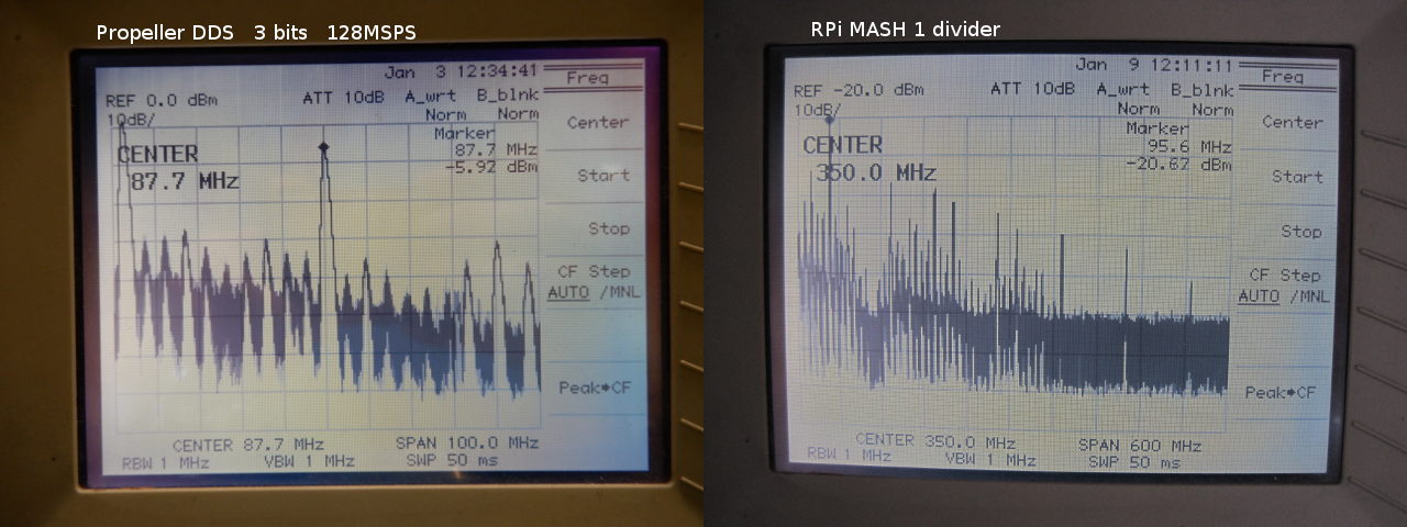
Fastest DDS (128 MSPS) and FM Transmitter
 SaucySoliton
Posts: 585
SaucySoliton
Posts: 585
in Propeller 1
Currently 3 bit output at 128 MHz sample rate. Available here: https://github.com/SaucySoliton/propeller-dds
The 3 bit output works well with the composite video DAC resistors on many Propeller boards. Signal purity is fairly poor, so keep your antenna wire short. I get enough leakage with just a coaxial cable to my scope. Sound quality has the potential to be very good once pre-emphasis is added as the DDS has tuning steps much smaller the 1 Hz. The high sampling rate should allow good signals below 20MHz with a simple RC lowpass filter.
While the counter PLL can generate any frequency from 500 kHz to 128+ MHz, the list of jitter-free frequencies can fit on one page. This is a frustrating limitation for RF projects. A little while ago I did some calculations for using the video generator to output a pre-calculated sine sequence. While this is useful for many more frequencies, it would not be usable for local oscillators for HF. The tuning steps were, for practical purposes, random, and could be as large as several kilohertz. One of the strengths of direct digital synthesis is very fine tuning resolution. So I began an investigation into the feasability of a proper DDS.
I decided to target the highest clock sample rate possible. This meant using the video generator to output pre-calculated groups of samples. 32 samples is the maximum, assuming each cog only outputs 1 bit. Also, it would be nice to access the hub every once in a while for frequency changes, for application like an FM transmitter. The video generators need to be synchronized exactly. It is necessary to fit the hub access between 2 WAITVIDs. Each cog's hub access is staggered by 2 clocks. This forces an additional trade-off between sample rate and number of bits. If the hub access was eliminated, it would be possible to synchronize any number of cogs together.
Why is the last one 5 MS instead of 4? Recall that the Nyquist theorem says signals exceeding half the sampling rate cannot be perfectly reconstructed. They will alias to a frequency less than half the sampling rate. So, there is no logical reason to program a frequency that exceeds half the sampling rate. We could extend the table to one and a half cycles and 384 steps and only need to mask the accumulator every other addition. For groups of samples we can't assume we will only advance half the wave at a time. We could still use this trick with 2 or more full tables of 128 steps. I chose not to use the shorter table at this time.
Some of the implementations previously published shift the accumulator to extract the MSBs with MOVS and then shift it back. We can save 2 instructions by leaving it in the shifted position. We have to use one of the instructions gained to clear the MSB carry bit so we stay in our table. But as noted above, it's possible to not need it every time. We can use ADDX to transfer the carry from LSBs to MSBs. A slight complication of this is that the carry is not added until the next addition. This would sometimes introduce an error of 1 step in the output. We could fix this by adding an offset to the accumulator so the carry happens one cycle sooner. That is simply adding a phase shift to our signal, which can be ignored for most applications.
The FM transmitter is nowhere near finished. I just it together to test the DDS. Sound quality is not so good without pre-emphasis. Signal purity is bad, but perhaps slightly better than Rasperry Pi before I fixed it. I wish the Propeller had PLLs like the Raspberry Pi. The fractional N PLLs in that chip have a clean signal AND a wide enough loop bandwidth to modulate FM stereo. I will probably make a version of the transmitter that uses the Propeller PLL just to test the signal quality.
The 3 bit output works well with the composite video DAC resistors on many Propeller boards. Signal purity is fairly poor, so keep your antenna wire short. I get enough leakage with just a coaxial cable to my scope. Sound quality has the potential to be very good once pre-emphasis is added as the DDS has tuning steps much smaller the 1 Hz. The high sampling rate should allow good signals below 20MHz with a simple RC lowpass filter.
While the counter PLL can generate any frequency from 500 kHz to 128+ MHz, the list of jitter-free frequencies can fit on one page. This is a frustrating limitation for RF projects. A little while ago I did some calculations for using the video generator to output a pre-calculated sine sequence. While this is useful for many more frequencies, it would not be usable for local oscillators for HF. The tuning steps were, for practical purposes, random, and could be as large as several kilohertz. One of the strengths of direct digital synthesis is very fine tuning resolution. So I began an investigation into the feasability of a proper DDS.
I decided to target the highest clock sample rate possible. This meant using the video generator to output pre-calculated groups of samples. 32 samples is the maximum, assuming each cog only outputs 1 bit. Also, it would be nice to access the hub every once in a while for frequency changes, for application like an FM transmitter. The video generators need to be synchronized exactly. It is necessary to fit the hub access between 2 WAITVIDs. Each cog's hub access is staggered by 2 clocks. This forces an additional trade-off between sample rate and number of bits. If the hub access was eliminated, it would be possible to synchronize any number of cogs together.
Other possible configurations for the DDS code, not yet implemented:
      loop clocks  bits/cog   bits total
128MS     20          1           3 (maybe 4)
 80MS     32          1           4+ ?
 64MS     20          2           6 (maybe 8)
 40MS     32          2           8+ ?
 16MS     20          8           8+
  5MS     16         32          32+
Assumes a 256-step sine table
Why is the last one 5 MS instead of 4? Recall that the Nyquist theorem says signals exceeding half the sampling rate cannot be perfectly reconstructed. They will alias to a frequency less than half the sampling rate. So, there is no logical reason to program a frequency that exceeds half the sampling rate. We could extend the table to one and a half cycles and 384 steps and only need to mask the accumulator every other addition. For groups of samples we can't assume we will only advance half the wave at a time. We could still use this trick with 2 or more full tables of 128 steps. I chose not to use the shorter table at this time.
:inline1    mov   outa,0-0
            addx  accu,tw  wc
            andn  accu,#%1_0000_0000
            movs  :inline1,accu
:inline2    mov   outa,0-0
            addx  accu,tw  wc
            movs  :inline2,accu
            jmp   #:inline1
Some of the implementations previously published shift the accumulator to extract the MSBs with MOVS and then shift it back. We can save 2 instructions by leaving it in the shifted position. We have to use one of the instructions gained to clear the MSB carry bit so we stay in our table. But as noted above, it's possible to not need it every time. We can use ADDX to transfer the carry from LSBs to MSBs. A slight complication of this is that the carry is not added until the next addition. This would sometimes introduce an error of 1 step in the output. We could fix this by adding an offset to the accumulator so the carry happens one cycle sooner. That is simply adding a phase shift to our signal, which can be ignored for most applications.
The FM transmitter is nowhere near finished. I just it together to test the DDS. Sound quality is not so good without pre-emphasis. Signal purity is bad, but perhaps slightly better than Rasperry Pi before I fixed it. I wish the Propeller had PLLs like the Raspberry Pi. The fractional N PLLs in that chip have a clean signal AND a wide enough loop bandwidth to modulate FM stereo. I will probably make a version of the transmitter that uses the Propeller PLL just to test the signal quality.
1280 x 480 - 97K
Comments
I currently need to allow 12+ cycles for hub access because the hub windows are staggered but the waitvids are not.
The FM transmitter is in progress. I'm not eager to write the filtering and pre-emphasis code since the Propeller has no floating point or hardware multiplier. Both the DDS and the Propeller PLL have enough bandwidth for FM stereo with RDS.
Other applications I had in mind were QRP transmitters, WSPR beacons, and local oscillators for receivers. Whether this code generates a cleaner signal than the PLL is yet to be determined. Also, I just realized that the counters connected to a DAC will generate a sawtooth signal at an 80 MHz sample rate.
It's not looking good for the DDS. Why did I do this? >:(
PLL jitter is starting to become more visible.
This is why we don't use the Propeller as a transmitter. A bandpass filter would not be able to clean the PLL output unless it had a very high Q, such as a cavity filter or crystal filter. An external PLL would work, as Phil has done.
The sidebands on the DDS signal might be due to the low 3 bit resolution or too much error at the end of the 32 sample tables at peak modulation. Other possibilities include the zero order hold in the modulator cog, changing the output frequency in a stair-step pattern. It could also be caused by a lack of low-pass filtering on the modulator's input. Capturing the DUTY output of one counter with another counter may introduce some high frequency noise. I'll be doing some tests without modulation to help narrow down the cause.
You never know these things until you try.
In a previous post the FM transmitter SFDR was about 27dB.
The 128MHz video clock SFDR is 25dB. It appears that all of the noise at 200-300kHz from the carrier is from the video clock.
The peaks near 500kHz might be worse with the DDS, but keep in mind that the DDS runs 3 PLLs together.
The triangular sidebands appear to be VCO noise. While disappointing, this is not surprising as the Propeller PLLs do not have the circular inductors commonly seen on RF VCOs. Cascading 2 PLLs seems to make things worse by 10dB. There are 2 ways to avoid this: 1.We could use an external crystal oscillator. 2.Don't use the video generator. Unfortunately the video generator can only be driven with the counter in PLL mode. The counters can output a 2-bit signal, more on that later. With interleaved cogs writing OUTA we are limited to 20MSPS although in this region the PLL phase noise isn't so bad. If we avoid using either PLL, the signal should be very clean.
The Propeller's crystal oscillator looks good.
-Phil
Interesting idea! Sounds great for HF frequencies. I don't see how it helps for wideband FM. With a low frequency crystal we would still need a PLL to get the frequency up. The output should be close to acceptable though. With a high frequency crystal we probably couldn't get enough deviation.
Has anyone connected the oscillator pins to a tank circuit instead of a crystal?
It might be possible to clean up the phase noise by using an external register driven by an external crystal oscillator. That register could be part of a DAC chip.
Never mind. The registers are built into the Propeller. 8) They're part of the counter feedback circuit. We need to waste some pins for the register inputs. The could also be issues with the delay from routing signals to a pin and back. The output sampling rate must match the system clock, but the external register has the same limitation.
The narrowband SFDR is 34dB. Previous version was 27dB. This is reasonable considering the previously measured difference between 1 PLL and 2 cascaded PLLs. For both tests I was using the system PLL for convenience. If the Propeller was clocked by an 80MHz crystal oscillator the VCO noise should vanish. The other spurious signals should decrease as more bits are added. That will be easier now with the relaxed timing at 80MSPS compared to 128MSPS. Code will be uploaded after some cleanup. Stay tuned!
I will see if I can figure it out again ... or if it was one of my weird ideas that was never going anywhere .. again
And then I find these -
https://www.banggood.com/35M-4_4GHz-PLL-RF-Signal-Source-Frequency-Synthesizer-ADF4351-Development-Board-p-1129041.html?rmmds=search&cur_warehouse=CN
Makes all all the experimenting seem a bit pointless - Use the Prop for the control/display stuff and leave the spectral purity to faster DDSs
It was either going to be pure genius ... or ....
Any way I do not have any of the analog TV tuners anymore
Yes, HF Xtals have quite narrow pull range, but Ceramic Resonators can be used for more pull range than a Crystal.
Checking MEMS VCTCXO's I see they offer :
Pull Range PR ±12.5, ±25, ±50 ppm
Control Voltage -3dB Bandwidth V_BW – – 8 kHz
So still quite small pull range.
Any CMOS inverter oscillator can use a LC just fine, however, you need to find a high Q inductor, which is no easy task.
For direct 80MHz clocking experiments, to skip Prop PLL noise, you could look at the Si5351 ? - Adafruit have a $8 breakout module for this part.
The VCO version of this part specs 10kHz bandwidth, and 30 ~ 340ppm pull range user selectable.
Some of the SiLabs parts allow small continual steps, Si514/544/549 indicate within ~ +-950ppm as being ok.
Not sure how the cheaper Si5351 stacks up, but an alternative could be to update just the fine-trim registers via i2c for narrow FM modulation ?
Addit: checking Digikey, and https://www.silabs.com/products/timing/lookup-customize
gives these stock items
Part Number: 514CBB000112AAG Product Si514 Description Any Frequency I2C Programmable XO
Frequency A 10 MHz I2C Address (Hex Format) 55 Format CMOS
Supply Voltage 3.3 V Temperature Stability / Total Stability 25 ppm / 50 ppm
Package Option 5x7 mm
Part Number: 514FAA000115BAG Product Si514 Description Any Frequency I2C Programmable XO
Frequency A 125 MHz I2C Address (Hex Format) 55 Format LVDS
Supply Voltage 2.5 V Temperature Stability / Total Stability 50 ppm / 100 ppm
Frequency Range 100 kHz - 250 MHz
Package Option 3.2x5 mm
Part Number: 514BBC000932AAG Product Si514 Description Any Frequency I2C Programmable XO
Frequency A 70.656 MHz I2C Address (Hex Format) 1D Format LVDS
Supply Voltage 3.3 V Temperature Stability / Total Stability 25 ppm / 50 ppm
Frequency Range 100 kHz - 125 MHz
Package Option 5x7 mm
The 514CBB000112AAG looks Prop-useful (3.3v, CMOS drive, 10MHz default)
The Propeller 1 PLLs have a significant amount of jitter. It's a big problem for radio transmitters. Thankfully it's easy enough to use an external oscillator for the system clock. The oscillator I used was the MXO45HS-3C-80M0000 It's a 5v part, but is seems to work fine at 3.3v.
Another minor problem is that the video generator can only be clocked from a PLL. We can work around that by following the video generator output with a flip-flop, as long as that flip-flop is clocked by a clean clock source that's phase locked to the video generator clock. Some counters in feedback mode will do the trick. They are clocked by the system clock, and the video generator clock is phase locked to it. We just have to waste pins to route the video generator output through the counters.
Each cog generates 1 bit of data. So the 3 bit output uses 3 cogs and 6 pins. But you can have an 80MSPS direct digital synthesizer using only through-hole parts!
SFDR has improved from 34dB to 40dB. The signal shown is being modulated for an FM transmitter. The remaining noise could be from having only a 3 bit D/A converter, or as a result of the modulation. The audio is acquired by counting the duty cycle of the audio output pin driven by another cog. From this discussion on the P2 we've found that using a rectangular window is far from optimal. forums.parallax.com/discussion/comment/1457413/#Comment_1457413 The signal quality could likely be improved more by adding more bits to the DAC and by using a triangular or quadratic window on the audio input. I'm probably not going to test more bits due to lack of enthusiasm. The window function is easy to adjust. Or I could just turn off modulation to check the carrier itself.