

Question on UC3842B Current Mode Controller
 mojorizing
Posts: 249
mojorizing
Posts: 249
I'm troubleshooting a power supply that uses an 8 pin UC3842. The PS output drifts from a rated 24vdc to around 16vdc and it's on a high voltage board for a welder. It supplies power to 2 muffins fans, the gas solenoid valve for TIG mode, among other things. The problem occurs even before I hit the TIG pedal - the welder is just powered on and sitting idle, no welding going on.
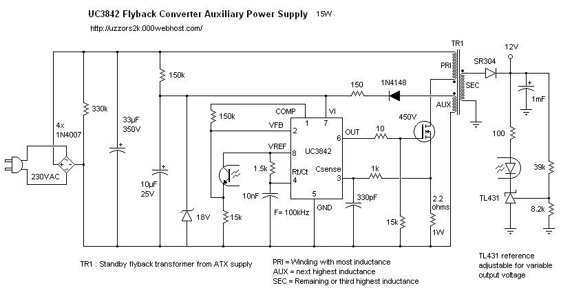
Below is an example of a circuit that I'm used to seeing with output feedback via an opto isolator back to the input side on VREF and VFB.
However, the circuit I'm dealing with is more like Figure 35 from the PDF from the Onsemi's spec sheet here....onsemi.com/pub_link/Collateral/UC3842B-D.PDF
Seen here
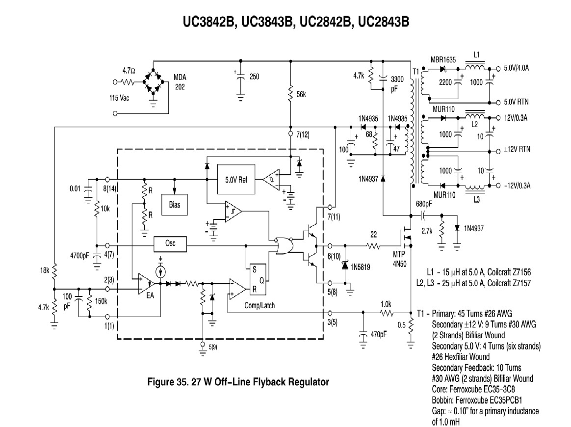
In this circuit how are the various voltages on the outputs (5vcd, 12vdc,-12vdc) maintained? The only circuit I see is the voltage divider made up of 18K and 4.7K on the pin 7 , Vcc. I see a corresponding decrease at pin 2 when the voltage at pin 7 (one secondary of the xfrmr that supplies the UC3842) drifts lower, but the pulse width out of pin 6 does not increase to compensate. What I'm I missing?
Below is an example of a circuit that I'm used to seeing with output feedback via an opto isolator back to the input side on VREF and VFB.
However, the circuit I'm dealing with is more like Figure 35 from the PDF from the Onsemi's spec sheet here....onsemi.com/pub_link/Collateral/UC3842B-D.PDF
Seen here
In this circuit how are the various voltages on the outputs (5vcd, 12vdc,-12vdc) maintained? The only circuit I see is the voltage divider made up of 18K and 4.7K on the pin 7 , Vcc. I see a corresponding decrease at pin 2 when the voltage at pin 7 (one secondary of the xfrmr that supplies the UC3842) drifts lower, but the pulse width out of pin 6 does not increase to compensate. What I'm I missing?
831 x 438 - 48K
1164 x 870 - 187K
Comments
My plan is to replace the UC3842B and the caps associated with the PS on the old board.