

My RM-101 ARM robot

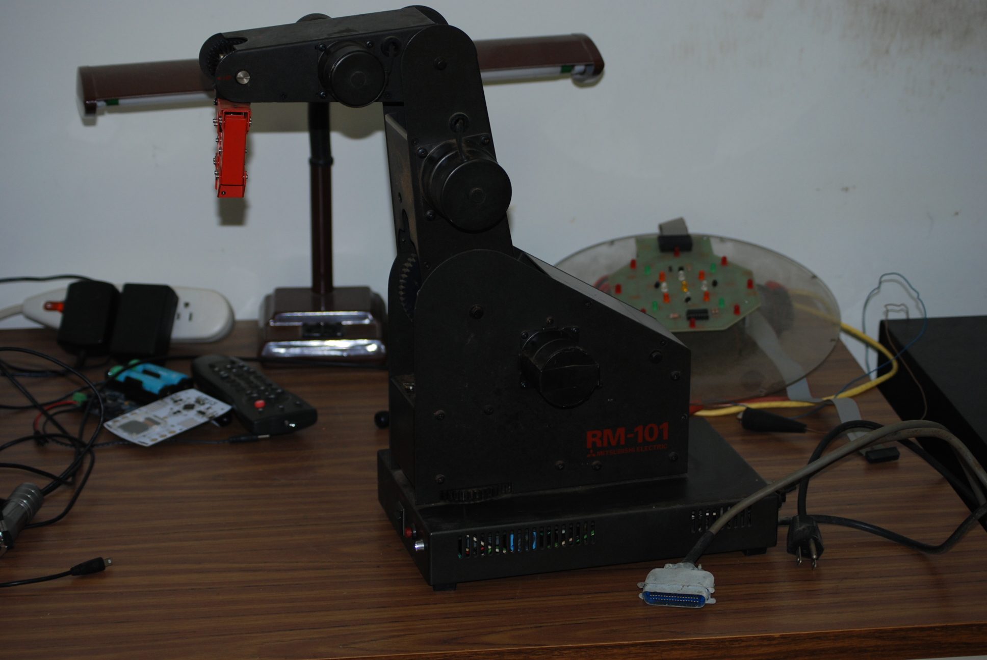
Since I was taking pictures, here is my RM-101 robot. This will also be a project, not sure how I will do this one though. As you can see, in the first picture, it has a parallel connector. That is the only way you can talk to the robot.
I think the Propeller could handle a parallel connector(printer port), but I am not sure what the circuit would look like. And of course I would be writing a program in PropGCC, so Iam not even sure what the C code would look like to do this. I know of a web store that sells parallel port break out boards, then I would need some wires going to a breadboard, which would connect to the Propeller pins. Since the parallel port is sending one way, I wonder if it needs a common ground, plus I am assuming that I would be dealing with just eight wires plus ground if necessary. lot to think about with this project.
Ray
1936 x 1296 - 657K

1936 x 1296 - 666K

1936 x 1296 - 680K

1936 x 1296 - 683K

1936 x 1296 - 688K

1936 x 1296 - 695K
Comments
The first reference I picked up with the Centronics connector pinout shows the strobe as pin 1, then eight data bits on pins 2-9 (LSB on 2) and ground on pins 18-25. You'll have to look at the robot docs to see if it uses any of the other pins. You'll also need to level shift, since the parallel port expects TTL levels.
Some applications kludged the printer port for bi-directional communications using the handshake lines, so you need to be sure you know how the port on the robot is set up. Definitely read the manual. If you don't have that, I found this project online where they did the hard work of disassembling the robot's Z80 firmware to figure out the commands for you: http://shackspace.de/?p=3284
Also, I do have the RM-101 original manual. What am I getting myself into, next thing you know I will want to start up a company, and buy some more robots, ... , time to go lay down and take a nap before I ...
Ray
Good luck with the project, or at least enjoy your nap!
Bob
Many years ago, some 'expert' described robotics something like this:
'Tie one arm behind your back, smear vaseline on your glasses, and assemble something complicated using chopsticks.'
Actually what you need for this is to be able to setup a repetitive state. If recall it does not have any memory of its own, so you have to have an external device to that feeds it a program, but I could be wrong about this. I will have to read the manual pretty soon and figure out exactly what the capabilities are.
Ray
Often devices which use Parallel ports have many shared pins. I think there were at least six (I'm remembering nine) ground lines used by the CNC controller I have.
I cut an old parallel cable and soldered some normal 0.1" headers onto the wires I needed.
You should be able to see the 2x8 black connector in the upper center of this photo.
There's a right angle 2x8 male header on a small piece of proto board just to the left of the black female connector. The male connector is wired to a Propeller Proto Board.
The 3.3V logic from the propeller didn't control the stepper driver. I would need to use level shifters to make this hardware work.
I ended up using a different stepper driver which worked fine with the Propeller's 3.3V logic.
If you don't want to cut your parallel cable, you might be able to salvage a mating connector from on old printer. Of course it's been a while since printers had parallel ports. I still have two parallel port printers which still work (though I don't use them) but I've gone through several USB printers which are now sitting in one of my junk part piles.
As you noted, there's always the option of purchasing the appropriate connector.
Does the documentation list the pin outs?
There were some folks that took the same RM-101 and disassembled the code from the EPROM and control it from a script. They did have to hack the parallel port since it was not the original and documented the data so that might be of interest to you. This was posted on Hackaday as well
shackspace.de/?p=3284
The other option is to get a USB to Parallel cable to control it via a USB port.
https://amazon.com/IOGEAR-USB-Parallel-Adapter-GUC1284B/dp/B00018RT1E
Oddly enough, I recently worked for one of the largest Flash memory companies on the planet which is based in Japan and I was surprised to see their main SSD test fixture was controlled via a parallel port. I guess you use what you know.
I did find a Mini-ITX board with a centronics port on the board, in the basement, I think the board still works. I will have to try too get it running, maybe load up a small Linux distribution, and see if can get access to the parallel port. I am supposed to be retired, with these side projects it is starting to feel like work again.:-)
Ray