

Controlling AC Universal Motor (Blower) with a Propeller
 Duane Degn
Posts: 10,588
Duane Degn
Posts: 10,588
in Propeller 1
I'm trying to figure out a good way of controlling a blower with a Propeller.

The blower is the one shown above from Home Depot.
Duane Johnson posted some useful information here.
This is figure 6.9 Duane mentioned.
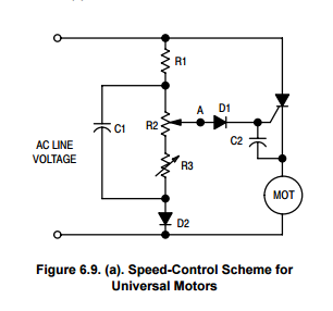
The above circuit is supposed to be useful when the universal motor is used to load which can vary. I figure the blower motor should experience a constant load so I think the circuit shown in figure 6.2 from the page 93 of the ON pdf should work fine.
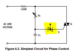
I don't understand the highlighted symbol. Based on the text of the pdf, I assume it's a symbol for a DIAC.
The guy I'm working with said he has used the circuit below to control blowers.
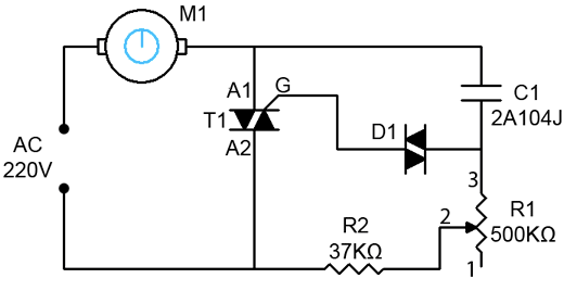
After reading in the ON Semiconductor pdf a bit, I figure the above circuit is pretty much the same thing as the circuit shown "figure 6.2".
In all these circuits a pot is used to control the speed. How do I replace the pot with a Prop?
Ben on his Applied Science channel used a LDR with a LED to control a drill with an Arduino. I figure I can use the same LDR/LED trick with one of the above circuits but I also wonder if there are other/better solutions.
Duane Johnson mentioned using a SCR (silicon controlled rectifier) but I don't think a SCR would be a good choice for this application since it limits one to half of the full power of the blower.
I looked for TIACs on Digikey and was overwhelmed with all the options. I confess to not understanding the various filter options.
Do any of you have a suggestion of which DIAC/TRIAC combo I should use with this 8 amp blower?
Any suggestions on a better way of controlling this blower with a Prop?
BTW, I'm aware one can use a variac to control something like this.
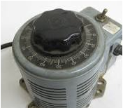
I just don't see an easy way of controlling a variac with a Prop.
The blower is the one shown above from Home Depot.
Duane Johnson posted some useful information here.
This is figure 6.9 Duane mentioned.
The above circuit is supposed to be useful when the universal motor is used to load which can vary. I figure the blower motor should experience a constant load so I think the circuit shown in figure 6.2 from the page 93 of the ON pdf should work fine.
I don't understand the highlighted symbol. Based on the text of the pdf, I assume it's a symbol for a DIAC.
The guy I'm working with said he has used the circuit below to control blowers.
After reading in the ON Semiconductor pdf a bit, I figure the above circuit is pretty much the same thing as the circuit shown "figure 6.2".
In all these circuits a pot is used to control the speed. How do I replace the pot with a Prop?
Ben on his Applied Science channel used a LDR with a LED to control a drill with an Arduino. I figure I can use the same LDR/LED trick with one of the above circuits but I also wonder if there are other/better solutions.
Duane Johnson mentioned using a SCR (silicon controlled rectifier) but I don't think a SCR would be a good choice for this application since it limits one to half of the full power of the blower.
I looked for TIACs on Digikey and was overwhelmed with all the options. I confess to not understanding the various filter options.
Do any of you have a suggestion of which DIAC/TRIAC combo I should use with this 8 amp blower?
Any suggestions on a better way of controlling this blower with a Prop?
BTW, I'm aware one can use a variac to control something like this.
I just don't see an easy way of controlling a variac with a Prop.
400 x 400 - 9K
306 x 286 - 18K
296 x 223 - 13K
520 x 268 - 21K
176 x 154 - 41K
Comments
This is another TRIAC option.
Here's a video showing how to use a IGBT transistor to control an AC load.
I couldn't find the exact transistor "IRG4PC50PbF" at Mouser but Mouser carries this one, which I figure should work.
It sure seems like this second video is treating the load like a DC load.
Any suggestions on which option is best for the blower?
A. Digital potentiometer? Don't know about isolation, though. Some of those circuits look like the pot is tied to AC power.
I guess you need to control the speed or you would just use a relay.
Yes, I need to be able to control the speed/power to the blower. I figure controlling the power is good enough for this application since the load should remain constant.
The two videos I posted use optoisolators. Probably both of the two methods shown in the videos should work well, I'm wondering if one method is better than the other.
I'm hoping for a second opinion on the IGBT part I linked to.
I'm also hoping for a first opinion on an appropriate TRIAC. The filters Digikeys shows when selecting a TRIAC went right over my head.
Or I KNOW, I KNOW! Get one of erco's robots to do it!
tc
-Phil
Silicon Chip has had a few articles on AC motor speed controllers that you may wish to look at.
Now this is the thing, if your Prop is going live then you could drive the triac directly through a transistor and the phase information can come into an I/O via another NPN with its base connected to AC through a couple of large value resistors (for mains ratings). The edges of the phase input are close enough to the zero-cross for you to time into the 1/120 second cycle (60Hz) before you trigger the triac. Once triggered for perhaps a few hundred microseconds you can release the trigger.
If now you want it isolated because you may connect to it serially then take all the proper precautions in addition to using optos both for drive and for phase info. Personally I would leave it live and connect to it safely via Bluetooth but that's because I use my Tachyon and I can talk to it and reprogram it on the fly which is a lot of fun, even from my phone.
Not that I think you're being serious, but since I knew so little about AC circuits, using a servo to control a Variac was one of the ideas which crossed my mind when I first started thinking about controlling the blower.
I have a feeling there are more elegant solutions.
I could find a full article on "induction motors" but the "universal motors" article only has the first page available for free. The universal motor control article looks like it would be interesting but the article appears to use a pot for speed control rather than a microcontroller.
Is there another Silicon Chip article you think would be useful?
I wouldn't have thought the Prop would have to monitor the zero-crossing. The circuits I've looked at use feedback from the AC line as a sort of automatic zero-cross detector.
I'm certainly willing to monitor the AC line with the Prop but I'm a bit surprised this is needed. Of course my being surprised isn't very meaningful. I don't know much about AC control.
The first video in my second post has this schematic at time 9:34.
I'm interpreting the circuit as using feedback from the AC line to detect zero-crossing along with a TRIAC driver driven with a PWM signal from the microcontroller. Would detecting the zero-cross using the Propeller provide better control?
As I mentioned, I'm not opposed to monitoring the AC line with the Prop, I just didn't think it would be necessary.
I suppose my other concern with monitoring the zero-cross with the Prop is my lack of knowledge on what part(s) to use. This article has several zero-cross dector circuits but I didn't see any reference to mains voltages in my initial skimming of the article.
Could a simple LED/phototransistor circuit be used as a zero-cross detector?
I think I have a couple SSR I could try.
I'll probably go the opto isolated route since I want the device to be able to communicate (over USB) with a PC.
I'll ask my LED/phototransistor question again. Is there any reason why I can't use a large value resistor with two LEDs to signal to a photodiode as a zero-cross detector?
Thanks for all the input.
-Phil
Thanks for clarifying. I incorrectly assumed the last schematic I posted allowed speed control without needing to track the zero cross.
Now please take this as a caution as you are asking lots of basic questions for this type of circuit which means you might not be aware of the different safety aspects of designing and working with mains voltages. I would not even suggest that you contemplate connecting the CPU end of the circuit to your PC via USB, I would hate to not hear you asking any more questions on this forum after an "incident" if you know what I mean!
In the YouTube video the guy mentions the DIAC isn't really needed but that it's useful when driving an inductive load.
Because I have LEDs and photodiodes on hand. I've used optocouplers to control outputs but I don't think I've ever used an optocoupler as an input. Though now as I type this I realize I likely have some optocouplers which are intended to be used with a MIDI interface.
I'm glad to hear you'd like to continue to see questions from myself. I certainly intend to keep asking them.
I think I understand the dangers of working with mains voltages. I've only done a few projects involving mains voltages in the past and these have been relatively simple relay control projects. I certainly don't intend to create a direct electrical connection between the mains voltage and my PC. I do think as long as the Propeller is only interfaced with the main voltage using optocouplers, the Prop should be safe to use with a PC.
I would hate to not hear Duane *answering* any more questions on this forum, as well.
You could always try controlling the speed by cycle count controlling the power to the motor. Use a zero crossing SSR or zero crossing optotriac driving the triac and cycle power on for x full cycles, off for y full cycles.
Especially if we have a complex mechanical arm arrangement (along with a gloved mechanical hand) from the servo to the Variac!
I know of motor controlled feet long linear "variacs" in large mains regulators, but this would be more like WWII tech vintage I would think!
@Duane: as long as you observe clearances and possible leakage or spark-over paths (due to transient events etc) as well as general layout and packaging then it should be fine. I also route an air-gap in certain parts of my pcbs as a precaution from those higher voltage spikes that can happen but the air-gap also helps if the board is not coated and accumulates dust and moisture which can form a high resistance path across the barrier. Of course you can add transient protection on the mains side to earth which will help as an anomalous event could do some damage if you happen to have your PC connected at the time. If it all seems like overkill then maybe it is but as long as we keep the "kill" over there, the better.
EDIT: don't use cheap strip board if you prototype, stick with FRB and universal double-side plated-through matrix board as the FRB is more stable and the PT holes provide mechanical stability so the soldered pads can't pop off the laminate and drift around. Strip board is ugly and you are always cutting tracks which can leave copper strands behind whereas matrix board like this is real easy to work with and much better.
I'll cut a slit in the pref board and have the DIP chip straddle the air gap made from the slit. I have some perf board I purchased from Sparkfun (before learning of less expensive options). Here's a link to the SparkFun perf board.
I don't think the latest forum software displays the Parallax font correctly so I'm including a screen grab of the schematic.
I don't have a 2W resistor so my plan is to use eight 1/4W resistors in parallel (with an appropriate resistance).
As I noted in the schematic, I plan to use 400 Volt 1N004 diodes. I figure the max voltage from the AC line should be 170V.
I'm hope some of you could let me know if this is a safe approach or not.
BTW, you must be a glutton for punishment drawing up schematics in Parallax font! Diptrace is free and the schematic editor is easy to use.
HINT: download LTspice for your schematics and you can simulate the circuit at the same time, observe waveforms and currents etc.
Here is a circuit that switches very close to the zero cross point.
Now that you mention it yes, I realize I can do away with the bridge rectifier. I wasn't thinking straight and I was concerned about the backwards voltage across the opto's internal LED. I didn't think about using a diode the way you suggested. I'm glad I asked about this again.
Okay, I'm hoping you had a slip of the the mind and were thinking of capacitors instead of resistors. Otherwise I'm very confused. I know capacitors in series reduces the capacitance while raising the voltage capacity but I thought with resistors one just worried about how much current was flowing through them?
I figure I'm shooting for about 10mA through the opto's LED. If I did my math correct the max voltage from 120VAC is 170V. To get 10mA from 170V I figure a 17K resistor should do the job. I figured I was safe ignoring the LED's voltage drop since it's so small compared with the overall voltage.
10mA at 170V gives a power requirement of 1.7W. I have a bunch of 1/4W resistors and I figure 8 of these in parallel will give me a resistor of 1/8 the resistance at eight times the power rating. Isn't this right? I have a serious misunderstanding about how resistors work if I'm wrong about this. Wouldn't eight 1/4W resistors in series still only be rated for 1/4W?
A 1N4148 is really okay? If I'm remembering correctly 1N4148 are little tiny signal diodes. They just seem kind of small for line voltages. As I think about this a bit I realize you're probably almost certainly right. Most of the voltage drop will be across the 17K resistor and only a small amount of current will be flowing through the diode. Ignore this paragraph, I figured out you're right.
I like and use Diptrace. There are other reasons for using the Parallax font. (These reasons aren't very good as I stop to think about them.)
Darn it, you're right again. I should do what you suggest. I'm just not anxious to learn a new software interface.
Is the purpose of the transistor on the Propeller side of the circuit just to invert the signal? I don't think I really care if the optoisolator inverts the signal. I'll just write the Propeller code knowing the input is inverted.
Thank you very much for taking time of give me your advice.
Do not use resistors in parallel on the line-in side. Put appropriate resistors in series for safety reasons.
-Phil
As for the diode just remember that it is only handling limited current in the negative cycle while the even smaller signal diode, the LED, is handling the current in the positive cycle. So the 1N4148 is probably at least 10 times beefier than the opto LED!. Your calculations for power are based on DC but here we are handling cyclic power and it is only at that peak for a very short time but you could calculate based on 0.707 RMS of that figure I suppose. If your LED resistor is too high as you have calculated then you won't achieve a sensitive turn-on close to the zero-cross point and besides the LED will handle this no problem.
The output transistor is to buffer the weak pullup on the opto as we want the opto to be sensitive close to the zero cross and this means reducing the opto collector current too, hence the large 220k but the output transistor only needs 0.6V min to switch so you end up with an output that switches close to the zero-cross point.
LT spice is very easy to use, hit R for a resistor, ctrl R to rotate it, C for cap, F3 for a wire. Use it for an hour and you will be comfortable with it.
Here's the opto circuit to get you started, just change values to see what happens.
And 8 2.2K resistors in series will give you 8 times (17.6K) the resistance and roughly 8 times the voltage rating, which is a better way to go.
Duh, I should have thought of that. Thanks.
I'm going to think about what you all told me and do a bit more research based on this new information. I'll have some more questions soon.
Thanks again for all your help.
I'm finally getting what you're all telling me about the resistors in series.
I'll try to come up with a good reason for my sanity slip later. Thanks for your patience.
The LED's forward voltage 1.2V (at 20mA).
Apparently I don't need to use resistors to limit the current based on the max voltage (170V) but I can use a lower voltage level to calculate the resistors to use reach a target current of 20mA. My earlier resistor value was based on 10mA LED current which I've found works fine for data transmission through the isolator. Based on what has been suggested here, I think I'd be better off shooting for a current through the LED of 20mA.
120V - 1.2V / 0.02A = 5940 ohm
Since I'm using 20mA instead of 10mA in my calculations, I need to use a different power rating for the resistors.
120V * 0.02A = 2.4 Watts (I figure I'm okay to ignore the voltage drop across the diodes in this part of the calculation.)
If I use 1/4W resistors: 2.4W / 0.25W = 9.6
I figure I need at least 10 resistors in series.
Since I want a total of 5940 ohms, wouldn't I want to use ten 594ohm (or there abouts) resistors?
Is this correct so far?
Edit: I'm not sure about these resistor power power calculations. I'll check these calculations tomorrow.
Thanks again for everyone's help.