

Project - Homebrew laser cutter
 JasonDorie
Posts: 1,930
JasonDorie
Posts: 1,930
During the MakerShed sale, I picked up one of these: http://www.makeblock.cc/xy-plotter-robot-kit/ along with the laser engraving kit.
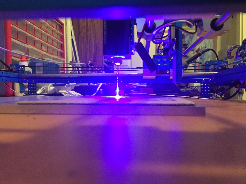
After playing with it a bit, I realized it was pretty under-powered (500mw) so I found a 6W diode laser and figured out how to drive it, and now I have this:

The buzzing you hear in the video is the cardboard vaporizing when the laser pulses hit it. If I run it over the aluminum plate underneath it there's no sound.
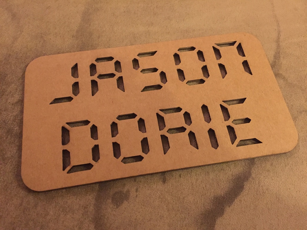
The video was taken through a pair of filtering safety glasses. Normally the beam is an intense blue that drowns out everything.
The board running it is an AtMega 328 at 16MHz, which is not powerful enough to interpret GCode in real-time while maintaining smooth motion. Currently the host software that sends GCode waits for the current command to complete before sending the next one. That means that if you're drawing smooth shapes made of lots of tiny line segments, the hardware shudders because it's constantly stopping and starting, waiting for the next command to arrive and parse.
I'm going to try to swap it out with a Propeller based board I'm designing now, which should be interesting. I'm hoping to have one cog parsing commands and pushing coordinates and coefficients into a buffer, then have another cog actually running the steppers, consuming the data from that buffer. It should be possible to do most of the work in the first cog so the second one has very little per-segment overhead.
After playing with it a bit, I realized it was pretty under-powered (500mw) so I found a 6W diode laser and figured out how to drive it, and now I have this:
The buzzing you hear in the video is the cardboard vaporizing when the laser pulses hit it. If I run it over the aluminum plate underneath it there's no sound.
The video was taken through a pair of filtering safety glasses. Normally the beam is an intense blue that drowns out everything.
The board running it is an AtMega 328 at 16MHz, which is not powerful enough to interpret GCode in real-time while maintaining smooth motion. Currently the host software that sends GCode waits for the current command to complete before sending the next one. That means that if you're drawing smooth shapes made of lots of tiny line segments, the hardware shudders because it's constantly stopping and starting, waiting for the next command to arrive and parse.
I'm going to try to swap it out with a Propeller based board I'm designing now, which should be interesting. I'm hoping to have one cog parsing commands and pushing coordinates and coefficients into a buffer, then have another cog actually running the steppers, consuming the data from that buffer. It should be possible to do most of the work in the first cog so the second one has very little per-segment overhead.
1044 x 783 - 290K
816 x 612 - 191K
Comments
I'm about to get the laser module for an xyzprinting 3d printer.
But, it's only ~500mW. It only engraves, don't think it can cut anything but super thin paper.
Whilst also..... very HOT!!!
Nice one Jason.
AWESOME, AWESOME, AWESOME!!!!! Absolutely love your video with very straightforward explanations of why the multi-core Propeller is a better choice for a piece of mainstream hardware like a CNC system.
Will you be sharing the schematics and code? I would love to make a Propeller based 20"x20" X/Y gantry.
Yes, I have no problem sharing. The board still has a design flaw that I have to fix, but I'll make everything public. The changes I made to the Orion firmware already are, and it's a very direct port of that code. The board itself was designed to be a direct swap for the Orion board, so I used RJ25 plugs to be compatible with their wiring and the pins match their stepper controllers.
The flaw is that the laser driver requires 12v to the enable pin to fully drive it. It'll light up with 3.3, but it's pretty weak. I'm going to add a teeny little FET (BSS138) to the board to handle that, and after that it should be fine.
I've attached DipTrace files for what I have so far, and I'd love feedback. My design & layout skills are pretty terrible, so anything constructive to help me improve is welcome.
I've attached the controller source too. It's a relatively simple GCode interpreter that treats Z in the range of 0mm to -2mm as the 0 to FULL pwm power output for the laser. I have two different blobs of code to drive the pwm. One uses the system timer in duty mode and the other just runs another cog. The first gives smoother control over the power, but if you're using a slow 3.3 -> 12v switch it won't work. The controller supports G0 rapid, G1 feedrate moves, G2 and G3 arcs, G4 dwell commands, and a bunch of setup, units, and homing M-code commands too.
It needs the PC-side host to run, and that thing is a Java app that has a whole Java runtime thing with it - it's 35mb and won't attach to a forum post, so I'm probably going to rewrite that at some point too, but for now it works.
You can download the GRemote thing from here: https://github.com/Makeblock-official/XY-Plotter-2.0
Great video!
I notice that the MakeBlock board has a lot more components than the PropLaser board. Why so much difference, if the PropLaser is a drop-in replacement?
@Seairth Based on the video at 2:21 and 3:20, he is only using two connections at this time. (X and Y?) Maybe the extra wires to turn on the laser?
I think five connections would be enough for the time being, adding Z-axis and some homing switches.
As always, Jason has produced a work of art!
A work of art? Have you looked at the layout?