Model Train Speedometer and Odometer
A SIMPLE scale speedometer & odometer for a "O" gauge model railroad.
Introduction:
I thought it might be fun to know the model train speed and distance in scale miles on your track layout.
A quick search on the internet yielded limited results. Most of which were products that measures speed by using fixed points along the train track. The limitation being that the speed indicated was limited to the that one location along the track. I was looking for a rail road car product that would display the speed and mileage at any time along the train track layout.
This is going to be a gift for my Dad, and with limited commercial availability to buy one, it will be fitting to make it myself using a Basic Stamp, or the Basic Stamp 2 (BS2) micro controller. As a side note: to save a few dollars, the Basic Stamp itself would have been perfect for this project, but I am familiar with pbasic for the BS2, hence my choice.
Back to the internet, and after reviewing some examples and methods built from various micro-controllers, one of simplest methods is to use a hall effect sensor and a small magnet for this project. As it happens, Parallax has a hall effect sensor available to order from their web site, maybe a bit pricey, but convenient, and only one is needed.
Construction:
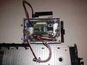
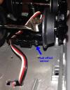
The hall effect sensor is very small and fits nicely glued below one of the axial's on the model train car. A small rare earth magnet is glued to the axial just above the hall effect sensor. As the axial and magnet rotates by the hall effect sensor, it causes changing "states" on the sensor's output.
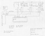
There is single pole double throw switch which selects the mode: Speedometer, or Odometer.
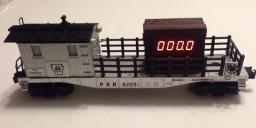
I used two "serial" L.E.D. displays, one on each side of the model train car.
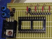
The model train car used was a "tie service car" which has a work shed on top of the deck, perfect for hiding the circuit board.
I used 1/4 inch wooden square doweling to simulate a stack of railroad ties to camouflage the L.E.D displays.
Theory:
There are a few different ways and pbasic instructions you could use with the sensor's output to determine speed and distance.
Again keeping it simple, I will use the "count" pbasic instruction to count the number of axial revolutions in a given time.
The advantage is the odometer keeps the total miles traveled while in either mode allowing to switch the display modes back and forth. The disadvantage is the speedometer resolution is 2 smph, and refreshes every 3.07 seconds. (A moderate compromise.)
The speedometer works by counting the number of revolutions in 3.07 seconds. The math: the number of revolutions in 3.07 seconds * 2 = the number of scale mph. Distance Traveled: 2.25 inches per revolution.
The odometer works by counting the number of revolutons, converting to tenth's,
and keeping a running total of the tenth's of a mile.
1 scale mile = 5280 ft. / 48 ("O" scale) = 110 ft. or 1320 inches.
1320 / 10 = 132 inches per tenth. 132 inches / 2.25 inches = about 59 revolutions per scale tenth.
Program Discription:
The program starts by making the unused pins of the BS2 outputs and declaring the varibles.
Then goes to the subroutine to reset and turn on the displays. If the mode switch is selected for the odometer mode, it will turn on the decimal point for the display of tenths of miles. (The decimal point is off for the speedometer mode.)
The main loop counts the number of revolutions in a set time of 3,070 milliseconds(3.07 seconds). Then calculates the smph by multiplying the number of revolutions counted by 2.
The next subroutine converts the number of revolutions counted to tenths of a mile and add them to the running total. It also saves the remainder of the division to be added to the next count (after the smph are calculated).
The main loop then checks the mode switch (a high or low on pin 15). If a 1 then update the display with the current total scaled miles traveled. If a zero then update the display with the current speed in scale miles per hour.
If no change in the count or mode then no update required then return to the main loop.
Note: The program is not optimized for program space, a few of the variables used for the "debug" display could have been removed, and the display routines could have been indexed to save on the duplication of them, but this program uses a modest amount of the BS2 programming space, so it is left as is.
Parts:
Lionel "O" gauge Pennsylvania Rail Road Tie Car #82091. Stock No. 6-82091
Spark Fun 7-Segment Serial Display, Red. Stock No. COM-11441 (two units)
Parallax:
Parallax Basic Stamp 2. Stock No. BS2-IC
Melexis 90217 Hall-Effect Sensor. Stock No. 605-00005
5 V LDO Voltage Regulator. Stock No. 601-00506
All Electronics:
400 point solderable bread board (cut to size). Stock No. SB-400
Neodymium magnet. Stock No. Mag-76
5.6k ohm resistor 1/4 watt. Stock No. 291-5.6K
my parts box:
10K ohm resistor 1/4 watt. (three)
.47 uF capacitor
47 uF capacitor
.1 uF capacitor
single pole, double throw micro switch (two)
single inline headers
single inline pins
9 volt battery connector
Home Depot:
1/4 inch square doweling, brown spray paint, two part 5 minute epoxy, 9 volt battery.
Note: a .bs2 file is a text file.
The interior of the shed was lighted with a single light bulb powered from the track through a pick-up on the trucks. I replaced the single bulb with two amber colored L.E.D's glued to the front and back windows to maintain the factory interior lighting. The L.E.D.'s are wired in series and are powered through the track by a diode and 1K ohm resistor.


Comments
You should consider submitting to Model Railroader or Model Railroad Craftsman.