

Suggestions to shield this Prop device?
 T Chap
Posts: 4,198
T Chap
Posts: 4,198
I sent a gadget to a client and unfortunately they installed put it inches from an air handler (above) and some type of air system directly below as well. Both of the air systems are metal boxes. My system( the black box) sits in the gap between them next to the electrical outlet. I can't tell from the pics they sent if there is a motor in the lower system, but there is definitely some motor controls on the top unit that is visible. The system is experiencing random problems, and I will be flying out to solve it next week. The wires that are ran to the module cannot be ran anywhere else, so I am stuck trying to solve the noise issue where it is. My first thought is to see if there is enough space in the front of the lower air unit so that the door will still close, and mount a plywood backing there vertically oriented and mount my box on it so that it is vertical and facing out. But there is still the proximity to the top air handler to deal with, and since it is random I can't sit and wait for hours to see if it is going to misfire. The other idea is to get some aluminum conduit(taken to ground on the AC outlet) and try to shield as much of the cables as possible.
Any suggestions on what to do here?
Any suggestions on what to do here?
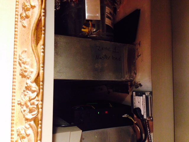
640 x 480 - 95K
Comments
How are the wires used. Power? if data, what sort? Can you switch to some sort of balanced signal if they're data lines?
Put it in a shielded metal case if not done already.
Shield where possible, ie wrap cables using aluminum tape & ground at one point.
Clamping diodes, terminating resistors, and capacitors on signal lines.
Good luck. Random noise problems are a bear. Even worse when far away.
https://www.fairchildsemi.com/datasheets/cd/cd40106bc.pdf
After the 40106 it goes to a PCF8574 8 input i2c expander IC. The prop is picking up random signals on these inputs from the 40106 during the i2c read. So the noise could be hitting the Cat5 before the box. The box is sheilded but they are keeping the top steel lids off so the top of the box is exposed, certainly putting the lids back on will help.
I am thinking of getting another steel enclosure, put my box inside it(11"x10"x3.25" OD), take the bigger box to earth. Then add some aluminum flex conduit around the cables to cover as much as possible, take the aluminum to earth.
I am going to check if there metal enclosures for the air have any voltage difference from the ground on the wall. If there is no difference, I am considering taking all that metal to ground.
You may have to do just that in order to understand exactly what the problem is. Then, you'll be able to apply the proper solution.
Will you have a scope available to investigate the suspect noise?
* A scope is a must
* The first thing I would look at is how well the micro is electrically isolated from the mains. Some of those transformers do not provide adequate galvanic isolation ...
* Diagnose with an isolated battery as the power supply if you need to
* Earth ground is NOT the same as micro controller ground ... Don't share them with one another
* Don't be fooled from what's an insulator versus a conductor ... To high voltage, an insulator is just a dielectric waiting for a parasitic capacitor to form. (especially with AC voltages)
What exactly does 'picking up random signals' mean ?
Is the PCF8574 10' away ?
You can do various things to harden serial links.
You can check data more than once, but clock noise to a HW device can be harder.
There, readback/check/retry can limit deviations to a short time, and it also gives a disturbance count.
Relays switching mains can generate signal edges sub ns that are very hard to eliminate entirely.
IF ina[0] == 1
   waitcnt(100_000)
       IF ina[0] == 1
          'this is a real input if it go this far
On the I2C read I am not checking twice, and this is easy to add another read in case the first detection was just noise. This may help with some misfiring issues, but if there is too much noise on the encoders, BLDC hall sensors then shielding and distance from the air handler is the only option I can come up with.
If using aluminum tape as suggested, how do you connect a wire to the tape? Alligator clips, or other circular hose type clamp around the cables/tape with a wire wedged inside to make contact with the aluminum?
A good scope is going to make it so much easier to narrow down the source of the problem that it is almost absurd to go without.
I suspect that you can get someone in just about any major city to rent you an oscilloscope for a day. Start out with the Yellow Pages and contact a local 'sound service' or 'radio-TV repair'. And there are local HAM radio clubs that might certainly know someone that is willing to rent a spare.
You need to pin down the exact failure modes, to really know how to attack this.
Try and cause a like-failure on your bench is a good start.
In the past, we've built a simple 'Mains Relay Wand' that has a DPDT Relay-oscillator (DC supply+NC contact+resistor+electrolytic cap make a chattering oscillator) and you switch mains on the other contact, into a short loop (all insulated, of course).
Wave that around your working unit, and try to mimic reported failure modes.
A misfire is more specifically a door system that is randomly opening for no reason.
An LCD Touch Screen that has 4 outputs(direct from Prop pins through a 1k resistor) into a 10' unshielded cat5.
At the box in the photo, the cat5 connects to the PCB>40106 Schmitt Inverter>PCF8574 I2C input. A 0.1uf bypass on the input to the 40106, along with a high value pulldown, maybe 200k.
I am thinking the noise is hitting the cat5 or the PCB from the compressor, and the Prop is reading an input as active. The inputs in question are active LOW. In this case, there are 4 inputs that are all sitting High until one of 4 graphics is touched on the LCD. One input going low ie %1110, %1101, %1011, %0111, is a trigger. But, for example %1100 is ignored or any other combination. Only one input can be low at a time or it is ignored. Seems like low odds for an actual read but it is happening. Considering the compressor is turning on and off a lot, and the random triggers are only a few times a week, maybe it's just a rare occurrence of the %1110 that gets read.
Beau's advice is excellent. Try to do everything he suggests in a methodical manner.
The CAT5 cable is at least twisted-pair. Can you change to shielded cat 5?
Is it possible the LCD touch screen is charged by all the stuff around it, and the Propeller is not doing anything wrong?
You might find that disconnecting the LCD -- but not the CAT5 results in stable behavior. If so, monitor the LCD for spurious outputs while disconnected.
Can you isolate the LCD from the rest? One possiblity is RS422/485 isolated drivers/receivers over twisted pair.
++++++++++++
Anything you do still need a scope to confirm the problem is resolved.
Putting a metal cage around your board may or may not help. One could try tin foil first to see if that clears up the problem -- look around restaurant supply or construction supply for heavy foil, easier to use.
How are you using the twisted pair to reduce noise? Check the connections, one may be cold soldered.
A bank of pull-up or pull-down resistors might make it all go away. These come in 4 or 5 resistors to a common pin that are easy to add to existing i/o. You just have to reach the common with a ground or Vcc.
To avoid waiting around...
Try starting and stopping the compressor. Also, try overloading that air filter with some dust. Lamp black or graphite dust from an art supply might do the trick, maybe too well -- be careful.
So the PCF8574 is IP only, and the touch zones are decided elsewhere ?
Are the other pins spare on the PCF8574 ?
Can you join some to GND to give a framing signal ? eg 1111 tells you nothing, but 1010bbbb will catch extra clock edges
You could try a polling voting system, where you run a Value and a Count.
If (ThisB == LastB) increment CountB, else reset CountB.
Only when CountB > some value, do you accept ThisB
- you have sparse valids, so this would be extremely noise tolerant.
If you can track and store the 'reset when <>', you get a feel for the noise failure rates.
The twisted pair won't really help eliminate noise unless there's a differential signal.
Lots of good suggestions here guys, many thanks.
jmg: LCD Touch Screen Prop Module <--- 10' cat 5 ----> Main board Prop module. (40106>PCF8474 ip only>Prop)
The client is saying there are random openings, but on reboot there is an open(Home), so I cannot rule out noise on the 3904 or RST.
hmm, I was going to ask if Reset was excluded...
Can you make a reboot less 'invasive' ?
Spike protection into RST means very short led Cs and series Rs near the package, to reduce the antenna effects. What package ?
Sounds like you want to fix this on one pass.
If you want to test it as a source of trouble, try generating smoke. Maybe just a big fat cheap cigar will do the trick. Or whatever a bee keeper uses to generate smoke.
If the air filter gaps and sparks, you will hear it -- and maybe able to see it. And you should get immediate confirmation that the Propeller is acting up at the same time.
Actually, if one of the pair is grounded and the other carries a signal -- that is some degree of shielding. Certainly not as good as differential signals, but it is shielding. The trick is to NOT have it grounded at both ends, which will cause a potential ground loop. This is somewhat similar to ribbon cables alternating signal and grounded wires as a means of shielding.
Good point. Is the CAT5 connected this way?
In that case I would convert those signals to currents instead of voltages. A 10 - 20 mA current signal is far more noise resistant than a 0-5V signal would be. It also allows for the use of of optical isolators if ground loops are a problem.
If the GND and 5V is powering the board that could be causing the problem, so additional filtering may also be needed.
So I would definitely consider trying to trigger a spark with smoke and watch what happens.
+++++++++
All the other stuff may be a waste of time if you keep getting high voltage sparks at random intervals.
That leaves those pesky long interconnects and ground current loops to worry about. Sorry I'm not much help there. Every case like this I have managed fix was different. And no matter how I thought about it theoretically the solution ended up being more of a desperate guess and trial and error. For example:
Recently a problem with a resetting Propeller whose reset pin was driven by another board a foot away was fixed with a stiff pull-up resistor and capacitor to ground close to the reset pin.
A data bus snaking around inside a rack and delivering random errors was fixed by replacing the normal flat ribbon cable with one that had twisted pairs. And ensuring correct terminations.
Random errors on a serial link between two items in the same cabinet was fixed when my scope showed me that the ground of one end was very "up and down".
One major thing is that every loop of wire is acting a turn of a transformer. The bigger the area enclosed by that loop the better external magnetic fields couple to it and induce unwanted currents in it. So the last thing we want is signals going out over one path and their return current coming back
via a far away path. Run signals and grounds close together. That what twisted pairs are for.
If you can use current loops instead of high impedance voltage signals I'm sure that would help.
It's at trying times like this that we are reminded that our circuits are not nice neat arrangements of lumped circuit elements, resistors, capacitors, transistors, chips etc connected together by wires that do nothing but connect what we want. No, our circuits are more like giant wobbly jellies where each part is connected to every other part by some electric/magnetic field. Ping one part and the whole thing wobbles.
Sometimes I think it's amazing anything ever works.