

Parallax Activity Bot controlled via Android application over Bluetooth

I will be using this thread to document my project for the creation of an Android application that can control a Parallax Activity Bot over Bluetooth. This thread will be devoted to the hardware set up and propeller code used. I will not be diving into the details of the Android code used in the project or how to program for Android.
To keep track of things I broke the project down into the sections listed below
Part 1 Parts List
Part 2 Schematic / Building the circuit
Part 3 Configuring the RN-42 Bluetooth Adapter
Part 4 Boe-Bot Propeller (Spin) code
Part 5 The Android App
Part 6 Results
Part 7 Final Thoughts
Part 1 Parts List
List of hardware I used in the project
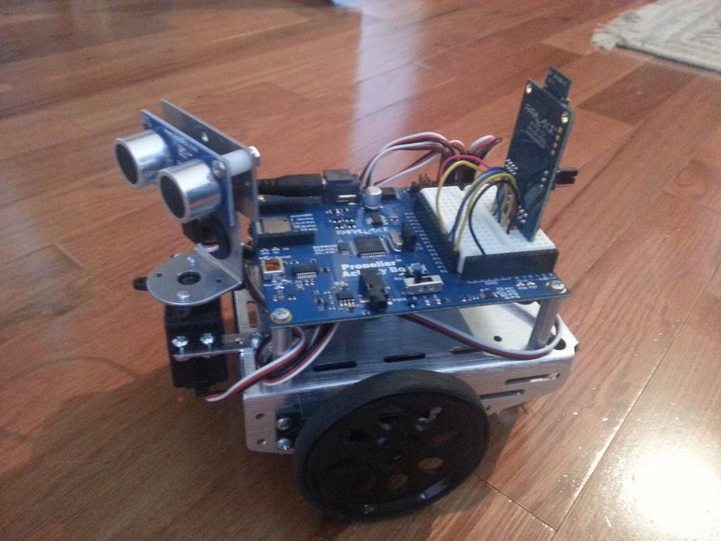
Attached is a picture of the assembled Boe-Bot with the Propeller Activity Board and the RN-42 Bluetooth Module. Wiring diagram / schematic to follow shortly.
To keep track of things I broke the project down into the sections listed below
Part 1 Parts List
Part 2 Schematic / Building the circuit
Part 3 Configuring the RN-42 Bluetooth Adapter
Part 4 Boe-Bot Propeller (Spin) code
Part 5 The Android App
Part 6 Results
Part 7 Final Thoughts
Part 1 Parts List
List of hardware I used in the project
- Parallax RN-42 Bluetooth Module
- Robotics with the Boe-Bot Parts Kit (I had the base as part of Boe-Bot with Basic Stamp Kit but replaced the Basic Stamp board with the Propeller Activity Board).
http://www.parallax.com/product/28124
Note to power the Propeller activity board with batteries you will need a battery pack of at least 7.5 Volts. The kit above comes with a 4 AA battery holder which provides a nominal 6 V which is the minimum voltage to power the board. While it will work when the batteries are brand new you will find that pack will quickly drop below 6V, especially under the higher current draw of powering the servo motors. Dont worry though there are several solutions to this problem:
Note to power the Propeller activity board with batteries you will need a battery pack of at least 7.5 Volts. The kit above comes with a 4 AA battery holder which provides a nominal 6 V which is the minimum voltage to power the board. While it will work when the batteries are brand new you will find that pack will quickly drop below 6V, especially under the higher current draw of powering the servo motors. Dont worry though there are several solutions to this problem:
1. If you already have a 4 AA battery pack you can add on a 5th AA battery using the adapter available from parallax which can be found here:
2. You can purchase a 5 AA battery holder here:
3. Or you can create your own custom battery adapter like I did which allows me to connect two 9V batteries in parallel providing even longer run times. Ill add pictures and a more detailed explanation in part 2.
- Propeller Activity Board
- For those who don't already have a BOE-Bot or Parallax Activity Board I would recommend going with the ActivityBot Kit. It comes with a 5 AA battery included, resolving the issue mentioned above.
- Any Android device running Android 4 or later with Bluetooth.
I used my Samsung Galaxy Note 2
Attached is a picture of the assembled Boe-Bot with the Propeller Activity Board and the RN-42 Bluetooth Module. Wiring diagram / schematic to follow shortly.
1024 x 768 - 92K
Comments
This post will focus on the electrical schematic used to build the circuit.
For detailed instructions on how to assemble to BOE-Bot please refer to the instructions provided by Parallax.
Building the BOE-Bot or Activity Bot
For the Robotics with the Boe-Bot Parts Kit see Chapter 3 of the link below. Additionally Chapter 2 give a detailed explanation of how to use and control continuous rotation servos as well as how to calibrate them for initial use. http://www.parallax.com/downloads/robotics-boe-bot-text
For those who have the ActivityBot, parallax has a website linked below with detailed instructions for the set up and tutorials.
http://learn.parallax.com/ActivityBot
Adding on the Bluetooth Adapter
I will go into the details of setting up the RN-42 Bluetooth Adapter for use with the Propeller microcontroller in Part 3 of this tutorial. For right now its important to just ensure that the voltage jumper is set to 3.3V setting and the Vin pin on the RN-42 is connected to the 3.3V header on the Propeller ActivityBoard. See Step 3 for the additional connections that need to be made between the ActivityBoard and the RN-42.
Building the Circuit
Attached is the schematic used to build the circuit required for this project. Additionally I have attached a picture of the assembled and completed circuit.
Step 1 connect the right servo to the 3 Pin header linked to pin 14
Step 2 connect the left servo to the 3 Pin header linked to pin 15
Step 3 Install the RN-42 into the breadboard on the ActivityBoard and make the following connections using jumper cables:
GND to the one of the open ground pins
VIN to one of the open 3.3V pins
RST to Pin 0
RX to Pin 1
TX to Pin 2
RTS to Pin 3
CTS to Pin 4
Creating a custom 9V battery adapter for use with the Propeller ActivityBot
The following will require basic soldering skills. Alternatively you can pursue the two other options discussed in Part 1 if you like.
Parts you will need
One 5.5mm O.D.x2.1mm I.D. coaxial DC power plug They can be found in a lot of online parts stores like DigiKey and Jameco or at the local Radio Shack:
http://www.radioshack.com/product/index.jsp?productId=2103614&clickid=prod_cs
One or more (I used 2 in my example) 9V battery adapters The also can be found online and at the local Radio Shack:
http://www.radioshack.com/product/index.jsp?productId=2062218&znt_campaign=Category_CMS&znt_source=CAT&znt_medium=RSCOM&znt_content=CT2032230
Assembly
The female DC power plug on the ActivityBoard is set up in a center positive configuration. This can be seen on the small schematic placed adjacent to the female adapter on the circuit board (See attached image). What this means is that the positive terminal on the battery should be attached to the center terminal of the male DC power plug, and therefore the negative terminal of the battery to the outer terminal of the plug. Almost all 9V batteries will label the positive terminal with an addition + symbol. In case you are unsure, the positive terminal on a 9V battery is the round male terminal while the negative is the female hexagonal terminal. Additionally the red cable from 9V battery adapter should be linked to the positive battery terminal.
Note You should verify all connections have been properly made using the continuity check feature of a multi-meter before connecting the assembled adapter to the Activity Board. Applying voltage in the wrong direction may break the Activity Board.