

Simple PWM to Analog Circuit (0-10vdc)
 laser-vector
Posts: 118
laser-vector
Posts: 118
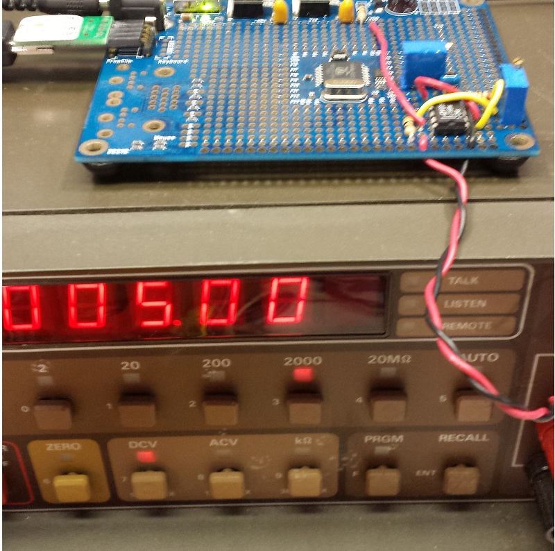
i just finished this simple circuit and am very satisfied with the result. The output is very stable and extremely linear!
just though id share as i didn't find much on parallax's forums when i was searching for this configuration.
Also any suggestions are greatly welcomed.

the above image depicts a circuit with two potentiometers, the pot connected to the I/O pin on the propeller is for tuning the pwm signal to a 0vdc - 3.3vdc output, the second is for tuning the opamp's feedback loop to achieve 0v - to the desired upper limit.

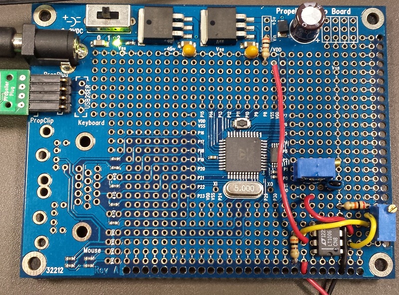
the code i used was a slight modification from the code found in the
AN001 - Propeller Counters v1.2 PDF:
parameter := 50
to any percentage of 10vdc you'd like.
i would love to be able to set the output not based on a 0 to 100 percent value, but rather using a long in hopes of achieving a 32bit D to A converter would it be possible or might jitter be an issue at certian values??
anyways hope you enjoy!
just though id share as i didn't find much on parallax's forums when i was searching for this configuration.
Also any suggestions are greatly welcomed.
the above image depicts a circuit with two potentiometers, the pot connected to the I/O pin on the propeller is for tuning the pwm signal to a 0vdc - 3.3vdc output, the second is for tuning the opamp's feedback loop to achieve 0v - to the desired upper limit.
the code i used was a slight modification from the code found in the
AN001 - Propeller Counters v1.2 PDF:
''Demonstration of PWM version of NCO/PWM counter mode
CON _clkmode = xtal1 + pll16x
_xinfreq = 5_000_000

VAR long parameter

PUB go | x , dir
cognew(@entry, @parameter) 'start assembly cog

  repeat
    parameter := 50 'a constant here locks to value x percent high
    waitcnt(clkfreq/1000 +cnt) 'wait a little while (1000 periods) before next update

DAT
''assembly cog fetches the value in parameter for PWM perecentage
        org

entry   mov dira, diraval 'set APIN to output
        mov ctra, ctraval 'establish counter A mode and APIN
        mov frqa, #1 'set counter to increment 1 each cycle
        mov time, cnt 'record current time
        add time, period 'establish next period

:loop   rdlong value, par 'get an up to date pulse width
        waitcnt time, period 'wait until next period
        neg phsa, value 'back up phsa so that it trips "value" cycles from now
        jmp #:loop 'loop for next cycle

diraval long |< 0 'APIN=0
ctraval long %00100 << 26 + 0 'NCO/PWM APIN=0
period long 100 '800kHz period (_clkfreq / period)
time res 1
value res 1
Change the value of:parameter := 50
to any percentage of 10vdc you'd like.
i would love to be able to set the output not based on a 0 to 100 percent value, but rather using a long in hopes of achieving a 32bit D to A converter
anyways hope you enjoy!

819 x 553 - 20K
800 x 794 - 223K

800 x 592 - 340K
Comments
I know you got this work but it's as if you don't totally understand the circuit. For instance you have a pot to make sure you get 0..3.3V from the PWM. But on this matter if this resistor was 1K or 1M you would still get 0..3.3V out. Then I see you limit the output resistance which means any loading will affect the output voltage so if you want to limit the output resistance then the feedback resistor should be connected to the actual output rather than the output of the opamp so that the opamp could compensate as much as it was able for various loads. I also can't see the need for a precision opamp especially considering that you have inserted a resistor into the output.
Whenever you use a pot for the gain circuit you are always limited by the long term tolerance of that device whereas it is very easy to calculate the required gain and use a few fixed resistors instead.
Gain = 1+ Rfb/Rdiv where fb is the feedback and div is the divider to ground. So you need an overall gain of 3.0303... which means the resistor ratio of Rfb/Rdiv = 2.0303....
Assume Rdiv is 10K then Rfb = 20.30K which is a 20K + 300R in series but there are many combinations possible. This fixed resistor method always works and is repeatable.
I normally just use a cheap LM358 fed duty-dac style for my 0-10V.
I've played around a little with DAC circuits like this, and ADCs also. At least in my experience, resolutions beyond 14 to 16 bits or so start encountering quite a lot of noise and drift.
So apart from settling time, I think that while the software may be capable of sending 32 bits of resolution, the resulting voltage probably won't have a dependable resolution much better than around 16 bits, if even that.
Correct, pots are best avoided, but if you must use one, there are things you can do to improve the circuit above.
i) Use the pot in ratio mode, so the wiper feeds the OP amp pin. Now, the absolute drift does not matter, only the differential drift between two sections of the same pot element.
ii) Use the pot to trim the span-error only, so the main gain is set by low-drift resistors and the pot uses a 20x/50x/100x feed resistor to its ratio, to vary the total gain. This drops the differential drive to apply to the trim-range only.
example might be a 2% trim range, and a 1% drift error, which becomes 200ppm when span-reduced.
-Phil
Not for production, sure, but for bench testing, sometimes easy variation is helpful.
We're getting picky here mate!
the pot connected to the I/O pin on the propeller is for tuning the pwm signal to a 0vdc - 3.3vdc output,
To add a little hysteresis, the output of the Op-Amp should have a large (470k) resistor feeding back to the (+). This helps keep the PNP out of it's linear mode of operation and essentially creates a switch mode power supply. You can eliminate any adjustment POT's altogether if you introduce a second PWM channel that can bias the (+) input of the Op-Amp.
Attached is an example... The "top" PWM on the far left controls the voltage ... 0-100% Duty = 0 to 10V ... The "bottom" PWM on the far left controls the bias to the Op-Amp. It's like adding a fine tune Potentiometer, only through software. A Duty cycle value of 25% here gave an approximate amplification of 3.03 ... (3.03 x 3.3V = 9.99V) <- resulting in a 0V to 10V observed output.
Note: Op-Amp needs to be powered from 12V supply in single supply mode.
Beau, I can see little advantage to your circuit versus the Op-amp circuit in the opening post. It still needs 12v, has highly asymmetrical output drive, it's slow, it won't work with a counter in duty-mode, it's highly sensitive to variation the the 12v supply, and likely draws more current. The only advantage I can see is that it could source a few amps depending on the PNP chosen. Though an op-amp circuit like whats shown here would still be my first choice for a high current Op-amp output.
Lawson
With 12V supply you will maybe need a Rail-to-Rail OPAMP to reach still 10V (the Transistor needs additional ~0.7 V):
Andy
The idea is to make the gain a bit higher and adjust the exact 10V output with scaling of to the PWM value. With that you can also compensate the error of the 3.3V regulator.
Andy
12V * 500mA = 6W, quite a lot of heat for a small transistor. What kind of load do you want to drive? If it's a motor or solenoid I'd do it with a mosfet and PWM, not with an analogue voltage. If you need true analogue output you could use some "high power" opamp that's used to drive speakers. But most of them aren't rail-to-rail. A single NPN transitor after a low power opamp also works but works single-quadrant only (it only sources current but doesn't sink). You could use two complementary transistors but then you need a negative supply.
It's an electric positioning device used in high-end animatronics. My understanding is that it's also used to move the control surfaces of air-to-air missiles.
I still guess that's some sort of inductive load (voicecoil linear motor). If it's only a quick hack then an opamp plus power transistor will do but needs a heatsink. If it's meant to be a real application google for class D amplifier. Those are designed to drive high power base speakers and are available in small packages that don't require much heatsinking.
I'd suggest you read the link from my post. The first circuit shown (labeled Figure 85) boosts a LT1210 1 amp +-15 volt op amp to run at +-18 volts and 10 amps with 1 MHz bandwidth. (it can easily do less if different components are chosen) Because of how the boosting trasistors are driven, it will have a nearly rail to rail output and should get within about 0.3 volts of the power rails. (well it would if the op-amp output was grounded instead of hooked to the output) Further down, another circuit shows how to pull the same trick with a faster dual op-amp. If you really need to run off a single supply, drive both sides of the load with this op-amp circuit (with one output inverted) and bias the output idle level of the circuit at half the supply voltage.
Lawson
All digital and good up to 2 ampsl. The inductance of the coil will smooth everything out. It works great, just PWM with compliment output to two of the bridges and hook the motor to them. 50% duty is center, (neutral position) and moving the duty very neatly moves the coil a proportionate amount. It gets even better with position feedback and a PID loop. If this is what you want, I'll dig up my notes..