Shop OBEX P1 Docs P2 Docs Learn Events
LANC control — Parallax Forums

LANC control

David BetzDavid Betz Posts: 14,516
edited 2014-04-05 21:52 in Propeller 1
My son wants me to make a LANC control for his camcorder and of course I want to do it with a Propeller (maybe the new Propeller Mini). I found some information on this on the web but it's for a 5V AVR chip. Here is the circuit diagram they suggest. How would I modify this to work with the 3.3V Propeller? I assume I'd need to change the zener diode and probably some of the resistors as well.
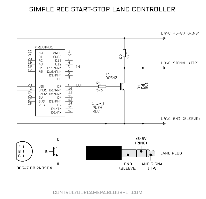
lanc.png
795 x 766 - 50K

Comments

  • Dave HeinDave Hein Posts: 6,347
    edited 2013-06-26 15:41
    I think all you need is a 3.3V regulator for power and a resistor on the signal input. I believe 2.2K on the input is enough to limit the current to the protection diodes. You can leave the zener at 5 volts. I suppose you could reduce the resistance to the transistor base to adjust for diving it at 3.3 volts, but it shouldn't matter too much.
  • David BetzDavid Betz Posts: 14,516
    edited 2013-06-26 15:46
    Dave Hein wrote: »
    I think all you need is a 3.3V regulator for power and a resistor on the signal input. I believe 2.2K on the input is enough to limit the current to the protection diodes. You can leave the zener at 5 volts. I suppose you could reduce the resistance to the transistor base to adjust for diving it at 3.3 volts, but it shouldn't matter too much.
    Thanks Dave. I thought the 5V zener was there to limit the voltage that could appear on the MCU input pin. Why wouldn't it need to be reduced to 3V or maybe 3.3V for the Propeller?
  • Dave HeinDave Hein Posts: 6,347
    edited 2013-06-26 15:53
    That would probably work also. Then you wouldn't need the resistor for the input. It depends on whether 3.3 volts is high enough for the camcorder signal.
  • Phil Pilgrim (PhiPi)Phil Pilgrim (PhiPi) Posts: 23,514
    edited 2013-06-26 16:13
    Here's a thread with an LANC object:

    -Phil
  • JonnyMacJonnyMac Posts: 9,098
    edited 2013-06-26 16:24
    It depends on whether 3.3 volts is high enough for the camcorder signal.

    LANC expects open-collector devices connected to it; the Propeller should float its TX pin to release the buss (idle, 1 bits), or pull it low (start, 0 bits). LANC is pretty easy; I built an little SX-based camcorder controller about six years ago.
  • David BetzDavid Betz Posts: 14,516
    edited 2013-06-26 16:47
    Here's a thread with an LANC object:

    -Phil
    Thanks for the pointer to the LANC code! I tried searching for "lanc" in OBEX and didn't find anything.
  • David BetzDavid Betz Posts: 14,516
    edited 2013-06-26 17:06
    Dave Hein wrote: »
    I think all you need is a 3.3V regulator for power and a resistor on the signal input. I believe 2.2K on the input is enough to limit the current to the protection diodes. You can leave the zener at 5 volts. I suppose you could reduce the resistance to the transistor base to adjust for diving it at 3.3 volts, but it shouldn't matter too much.
    Okay, I have another dumb question. The circuit I posted calls for a 2N3904 PNP transistor. I have a bunch of 2N3906 PNP transistors. Will that do?
  • JonnyMacJonnyMac Posts: 9,098
    edited 2013-06-26 17:42
    I have a bunch of 2N3906 PNP transistors. Will that do?

    No, that's a PNP; you'll want an NPN to pull the line low. You could use a small N-channel MOSFET, too.
  • Dave HeinDave Hein Posts: 6,347
    edited 2013-06-26 17:53
    The 2N3904 is an NPN transistor, so the 2N3906 PNP won't work as a replacement. As JonnyMac suggested you could just drive it directly from a Prop pin. That's the way it's normally done with I2C. A low would have OUTA low and DIRA high for the pin you're driving, and a high, or open collector mode, would done by setting DIRA low for that pin. You don't even need a zener diode if you use a resistor large enough to limit the current to the protection diodes. I believe the maximum allowable current to the diodes is 0.5 amps, so the resistor would need to be 12K or larger for a supply voltage of 9 volts. If 12K is too large for the camcorder you will need to use a 3.3 volt zener with a 4.7K resistor.
  • David BetzDavid Betz Posts: 14,516
    edited 2013-06-26 18:02
    JonnyMac wrote: »
    No, that's a PNP; you'll want an NPN to pull the line low. You could use a small N-channel MOSFET, too.
    Duh. I misread the schematic. I also have some "NPN-Type Switching Transistors" of some unspecified part number (came in a package of 15 from Radio Shack). Maybe they'll work.
  • JonnyMacJonnyMac Posts: 9,098
    edited 2013-06-27 09:11
    As JonnyMac suggested you could just drive it directly from a Prop pin. That's the way it's normally done with I2C.

    You *may* be able to do this. I tried this with an SX chip about six years ago and it worked fine, until I gave the command to turn off the camera. A few seconds later, the camera would come back on. It turns out that leakage through the pin circuitry was the culprit and would cause the camera to wake back up. I ended up buying the Sony SIRCS spec document and using the recommended circuit. It seems a bit overkill, but did work in the application which allowed the SX to be powered from the camera.

    In the attached schematic there is a net called WAKE -- pull this to ground through a normally-open button to wake a sleeping device.

    Please see post #15 for circuit, and post #20 for LANC object for the Propeller.
    572 x 719 - 73K
  • David BetzDavid Betz Posts: 14,516
    edited 2013-06-27 09:25
    JonnyMac wrote: »
    You *may* be able to do this. I tried this with an SX chip about six years ago and it worked fine, until I gave the command to turn off the camera. A few seconds later, the camera would come back on. It turns out that leakage through the pin circuitry was the culprit and would cause the camera to wake back up. I ended up buying the Sony SIRCS spec document and using the recommended circuit. It seems a bit overkill, but did work in the application which allowed the SX to be powered from the camera.

    In the attached schematic there is a net called WAKE -- pull this to ground through a normally-open button to wake a sleeping device.
    Thanks Jon! Looks like I'll have to collect a few more parts to make that circuit. :-)
  • dannyboyfldannyboyfl Posts: 4
    edited 2013-10-23 20:04
    Dave, I'm new to parallax... But I have been building Lanc Controllers using arduino... I'm not a pro on the electronics end... but a little better on the programming side of things... For the Arduino I connect the Lanc Pin to a single Pin on the arduino, avoiding using a NPN setup. Then in my script I would change that pin from a read to an out put and then to a read and so on... To be honest I have been just straight connection the lanc pin to the arduino pin... no pullup resistor, keeping the electronics as simple as possible...

    Might not be the best way but a very simple way.

    Here's a rough example.....

    // Start Reading Byte 0
    pinMode(lancPin, INPUT);
    delayMicroseconds(94);
    for (int i=0; i < 8; i++) {
    recValLo <<= 1;
    if (digitalRead(lancPin) == LOW)
    {
    recValLo |= 1;
    }
    delayMicroseconds(bitDuration);
    }

    pinMode(lancPin, OUTPUT); // Send Stop
    digitalWrite(lancPin, HIGH);
    delayMicroseconds(10);
  • JonnyMacJonnyMac Posts: 9,098
    edited 2014-04-05 07:55
    This past week I've been doing some late-night programming helping a friend with a LANC controller project. As it seems to be working pretty well, I've attached the first cut of my LANC object for review and suggestions. Please note that this is a work-in-progress and will probably change as I do more testing and write applications with it.

    The object is able to detect the presence of a LANC stream and, if lost (e.g., camera is unplugged or goes to sleep) reports that. A sleeping camera can be restarted with the wake_up() method, but this requires the Propeller to have its own power (i.e., not be powered from the camera 5v line which also goes off when the camera sleeps).

    This is working in my friend's project but I'll hold-off posting in in ObEx until we've really wrung it out. The interface between the Propeller and the LANC port is a simple 3.3v-5v level shifter that is typically used in I2C lines.

    [ Edit ] Updated schematic for clarity. This is the circuit deployed in my friend's project. Code removed for updating.
    800 x 419 - 62K
  • JonnyMacJonnyMac Posts: 9,098
    edited 2014-04-05 10:37
    It seems that any time I post an object within five minutes I discover reasons or decide to improve it. I've made a minor change to my LANC object: when there is no LANC signal the frame count is reported as 0 (false) -- makes it easier to deal with.

    The attached archive has the updated object and a demo program that I've used to control two different cameras (Sony and Canon). Some may note that the LANC codes in my demo are differeent than what one finds on the 'net. I determined these codes by connecting two off-the-shelf LANC controllers (Monfrotto and VariZoom) to my circuit -- this is possible because the LANC buss is open-collector/drain; the Propeller becomes a buss sniffer. Note, too, that I'm using FullDuplexSerial in the sniffer to eliminate any errors in my on LANC RX and TX code.

    Would love to know what others find.

    [ Edit ] D'oh! The codes I'm reading with the sniffer are different from what's published because I'm using a non-inverting interface -- other LANC interfaces invert the data in an out. I've pulled the code for a moment so that I can do software inversion; this will let others use commands from the Sony manual and from projects that use traditional UARTs (hence require a more complex interface).
  • David BetzDavid Betz Posts: 14,516
    edited 2014-04-05 11:25
    JonnyMac wrote: »
    It seems that any time I post an object within five minutes I discover reasons or decide to improve it. I've made a minor change to my LANC object: when there is no LANC signal the frame count is reported as 0 (false) -- makes it easier to deal with.

    The attached archive has the updated object and a demo program that I've used to control two different cameras (Sony and Canon). Some may note that the LANC codes in my demo are differeent than what one finds on the 'net. I determined these codes by connecting two off-the-shelf LANC controllers (Monfrotto and VariZoom) to my circuit -- this is possible because the LANC buss is open-collector/drain; the Propeller becomes a buss sniffer. Note, too, that I'm using FullDuplexSerial in the sniffer to eliminate any errors in my on LANC RX and TX code.

    Would love to know what others find.
    Thanks for the LANC circuit and Spin object. I've downloaded them and sent them to my son to see if he's still working on his camera control project. Looks like it should be pretty easy to use your circuit and code.

    Thanks!
    David
  • JonnyMacJonnyMac Posts: 9,098
    edited 2014-04-05 12:25
    David,

    I jut figured out why may LANC commands are different from the Sony manual and everything one finds on the 'net: everyone else is using an inverted interface -- the circuit I'm using is a non-inverting level-shifter. D'oh! I was wondering about this as I was scrambling all week trying to get my friend's project ready for NAB (on top of doing my day job). I'm going to update the driver so that one can use command bytes that one finds in other projects. I'm also going to put a link to my schematic so that others have it.

    I've been wanting to do this for a long time -- my friend's project forced me into it. Now I'm going to explore extracting timecode and other relevant information from the LANC stream.
  • PublisonPublison Posts: 12,366
    edited 2014-04-05 12:35
    Thanks Jon for diving into this!

    I have one Sony camera left to do some transfers, and this may help.

    Jim
  • JonnyMacJonnyMac Posts: 9,098
    edited 2014-04-05 14:24
    Okay! I fixed the inversion issue so codes from the Sony manual work with the object -- makes things much easier to deal with. I've updated the sniffer and my demo (which also sniffs); the demo allows camera control (what I needed for my friend's project) and shows standard VTR and camera status information. Next up I'm going to learn to extract the time-code from the LANC stream.

    Hmmm... this may be worth a Nuts & Volts article.
  • JonnyMacJonnyMac Posts: 9,098
    edited 2014-04-05 21:52
    With the interface sorted out and great information on this web page:

    -- http://www.boehmel.de/lanc.htm

    ... I was able to extract status and timecode information from the LANC stream.

    lanc_monitor.jpg
Sign In or Register to comment.