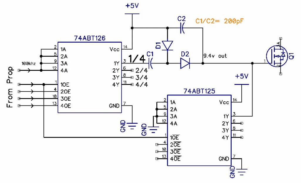
DIY Quad Charge-pump for high side n-mofet drive
 tonyp12
Posts: 1,951
At 18 cents each (IC) not to expensive to make.
http://www.mouser.com/Semiconductors/Logic-ICs/Buffers-Line-Drivers/_/N-50nahZscv7?P=1z0z7ptZ1z0slkvZ1z0sqwkZ1z0y3j8Z1z0yhi1Z1yzsrje&Keyword=ABT&FS=True&Ns=Pricing|0
I wanted to make so a high Prop pin = N-Channel mosfet ON, I ended up with this config.
If you are OK with the reversed, a hex open drain HCT05 would be OK instead of a ABT125 and use the ABT125 for charge pump.
plus it leaves you two pins extra for something else.
Or even a ULN2003, that give you an extra 3 pins.

I have not tested it. 200pF could be higher like 1nF etc
Maybe need a voltage tripler, if your VGS is not happy with 4v.
Picture is showing 1/4 of output stage.
dual-dual-series Schottky diodes and 4x array Caps make for less parts.
If you only have 3.3V available, you could use LVC versions and boost 3.3 to 6V (but is only a 2.7v highside VGS)
http://www.mouser.com/Semiconductors/Logic-ICs/Buffers-Line-Drivers/_/N-50nahZscv7?P=1z0z7ptZ1z0slkvZ1z0sqwkZ1z0y3j8Z1z0yhi1Z1yzsrje&Keyword=ABT&FS=True&Ns=Pricing|0
I wanted to make so a high Prop pin = N-Channel mosfet ON, I ended up with this config.
If you are OK with the reversed, a hex open drain HCT05 would be OK instead of a ABT125 and use the ABT125 for charge pump.
plus it leaves you two pins extra for something else.
Or even a ULN2003, that give you an extra 3 pins.

I have not tested it. 200pF could be higher like 1nF etc
Maybe need a voltage tripler, if your VGS is not happy with 4v.
Picture is showing 1/4 of output stage.
dual-dual-series Schottky diodes and 4x array Caps make for less parts.
If you only have 3.3V available, you could use LVC versions and boost 3.3 to 6V (but is only a 2.7v highside VGS)


Comments
That Voh is getting tough on the ABT125...
The better Hi side drivers include low drive lockout, as you do not really want too slow a turn-on with low impedance loads.
P-FETS are getting cheaper, and lower Rds, and they avoid the need for any charge Pump.
eg the AON6403 comes at 30V and 4.3mOhms
Despite the slow turn-on resulting from starting and stopping the charge pump, I think Tony's idea could enjoy some traction where cost is the overriding concern. My gut tells me that 200pF may be on the low side with a 100 kHz drive. OTOH, you don''t want to slow down the start-up more than you have to.
-Phil
My favorite IRF3708 MOSFET.
Gate Charge = 24nC
Drive amplitude = 5V
Drive frequency = 100KHz
C1 = 200pF
5V * 200pF = 1nC C1 charge transfer per cycle
24nC / 1nC = 24 cycles to charge the gate.
24 / 100_000Hz = 240uS
Quite workable if it's not switched to fast.
Raise the frequency to 1MHz and make C1 = 1nF then the gate charge time would be 5uS.
Seems a lot better.
Actually the switching time will be quite a bit faster.
Clearly this is not a rigorous calculation but probably in the ball park.
Duane J
http://www.mouser.com/ProductDetail/ON-Semiconductor/NUD3105DMT1G/?qs=sGAEpiMZZMsrr1kXJis%252bJ9gC9QYtqlpBYnbkRShrNLY%3d
(though having these on highside is not good for pull-down resistor or zeners?)
and two of a double dual-serias diodes:
http://www.mouser.com/ProductDetail/Diodes-Inc/SD103ASDM-7-F/?qs=sGAEpiMZZMuIUjt4yeP9c0AkDE5kF2Il%2fbaifs6KGd8%3d
and finally two 4 element array (pick your choice of pF):
http://www.mouser.com/Passive-Components/Capacitors/Ceramic-Capacitors/Capacitor-Arrays-Networks/_/N-5g91Zscv7?P=1z0x8hsZ1z0x7p2Z1z0x74kZ1z0x7weZ1z0x75aZ1z0t6fgZ1z0vhw8Z1z0vkpmZ1z0wpq0Z1yzh20z&Ns=Pricing%7c0
And a quad high-side relay driver is done.
Is it worth it?, maybe, there are probably ICs out there that does this for you.
Parts was selected on pin spacing , 0.65mm was weeded out as that is for more advanced smt solderers.