

Four input 5 volt to 3.3 volt level shifter
 Martin_H
Posts: 4,051
Martin_H
Posts: 4,051
I want to multiplex the input pin on a Propeller chip with four 5 volt sensors (e.g. four two pin ultrasonic sensors). My thinking is that I need four diodes coupled with a voltage divider. The diodes only allow the sensors to pull the line high, since they are wire OR-ed together any sensor can pull the line high, but the line is normally pulled low by a pull down resistor. The schematic looks like this:
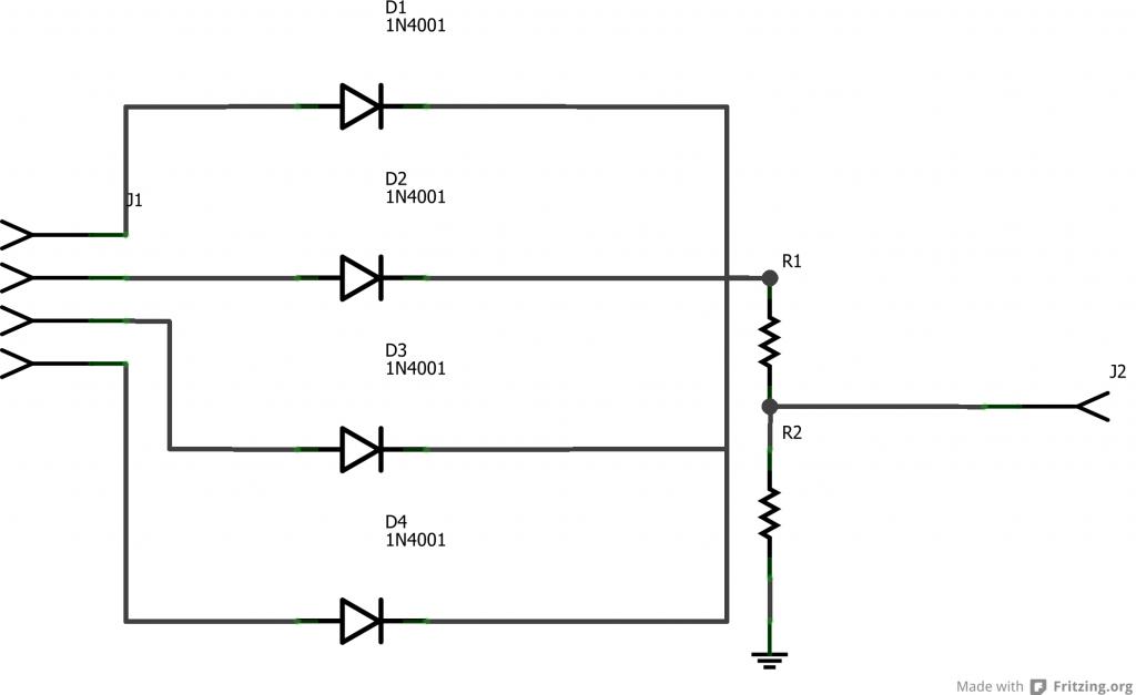
In use I pulse out the sensor's enable line and then read the multiplexed input line. That way I can use five pins instead of eight.
In use I pulse out the sensor's enable line and then read the multiplexed input line. That way I can use five pins instead of eight.

1024 x 627 - 32K
Comments
You could use two 1n914 diodes in series to get get as much as 1.4 volts of drop. They are also smaller and maybe even faster to respond.
At that point, you would not need any voltage divider. Just construct pairs in series and test for the actual voltage drop as there is some variation. The only other issue is whether you end up having two or more signals received at the same time, this is not really ORed as one input won't exclude another. You are really providing a mixed analog input.
You might just consider a logic chip to avoid mixed inputs. It may be possible to have a 5 volt logic chip powered with open collector output that is pulled up to merely 3.3v
http://www.electronicspoint.com/level-shifter-t137105.html
You may have to use a quad 2 input NOR chip to get four inputs and an uninverted output. But be careful to make sure your output is not inverted from what you want.
This is the chip I am think of, but I guess the intermediate outputs would require a +5 pullup; only the final output would be a 3.3V pullup.
http://www.cs.smith.edu/~thiebaut/270/datasheets/sn74ls33rev5.pdf
-Phil
This may help some. I was a bit uncertain about '5 volt tolerant inputs', but it eliminates the need for open-collectors as the chip can be powered by 3.3v and without the pullups. I guess you would not need NOR, just plain OR would work. But since you are building 4 inputs from pairs, either one does the same final result.
This is wrong!!
See post below.
Sorry.
Duane J
Agreed.
Martin, are these SR04 ultrasounds?
My thought was to use a separate Prop pin (output mode) for each trigger and then just tie all the echo pins together an watch it with a single Prop pin (input mode). It would probably be better to have a 10K resitor on each echo pin, but I think even if all the echo pins came through the same resistor things would work. (Assuming you'll trigger them one at a time.) This way it would take five Prop pins to use four ultrasound sensors. (I haven't tried this yet.)
Edit: The above is a very bad idea. Using only resistors may damage the ultrasound modules. See post #12 for a better alternative.
Duane, is the idea that the sensors that are low are no different from pull down resistors? While the one that is high pulls up the output? In effect you put the prop input in the middle of a voltage divider?
Yes. I guess what I'm worried about is a low output on one messing up the high output of another. So I was trying to find a way to isolate them from each other. But let the prop see all of them.
Sure, but you are mixing signals, not having one exclude others. I'm sure we can get into a passionate debate about using resistors versus diodes to create voltage drops, but neither is really the right solution for 4 alternating inputs going to one pin unless you are absolutely sure that any two or more signals won't overlap.
Isn't the objective to measure how long the signal goes high?
-Phil
I save my passionate debates for pseudoscience.
Loopy and Phil, I don't know if the resistor only method would work. I've been planning on trying this for a while. I have four ultrasounds in front of me so I'll give it a try. I'm glad Martin asked about this.
I misunderstood what Martin was looking for.
I was going off the message title.
Forget what I said in my message above.
Since Martin is combining 4 5V inputs to one pin his circuit would work just fine.
R1 should be about 10K. (Must be greater than about 3.3K.)
R2 should be about 100K. (Should be about 10 times larger than R1.)
There is nothing critical about the values
Almost any regular diode would work. I suggest the generic 1N4148.
Martin had 1N4001 diodes in the schematic.
While these 1 Amp diodes will work, it's usually preferred to use small signal diodes for this.
Duane J
Is there really a need for the voltage divider? Wouldn't a single 10K series resistor be enough (after the diodes)?
I don't mean to come across agumentative. Sometimes I think I know something (about an aspect of electronics) when I don't and I appreciate being corrected.
The diodes prevent zero volts from being seen by the Propeller pin. So you need r2 to pull down to zero volts when no output is active. You also need r1 to keep 5 volts away from the Propeller pin.
Duane J, thanks for the values for r1 and r2.
R2 is what is called a "Pull Down" resistor.
Any of the diodes can pull up the voltage to the pin through the 10K resistor.
However, if all diodes are low there is no current path to bring the pin low without R2.
R2, guarantees there will be a low on the pin when all diodes are low.
R2, can be almost any value from 39K to 1M or so assuming R1 is 10K.
R2 can't be to small or it would be a voltage divider and then the voltage
can't get high enough to be a high on the pin.
Hope that explains it.
Duane J
Very well.
Thank you.
If that is the case, you could still use the 4 sharing one pin -- but timing of ultrasonic pings in software are an equally important issue as there has to be some sort of rest period between each one to allow the microcontroller to get a good reading.
The issue of needing a pull down is a bit of surprise, but makes sense. So I guess diodes alone might be a bad idea.
The problem with using a logic chip solution is that each stage will introduce a time delay. If the OR gates hae a 25 nano second delay and you wire this up with 3 of them, you get a 50 nano second delay. With diodes, there may be nearly no delay.
-Phil
A Prop can monitor three echo lines with a single I/O pin using a 4.7K resistor on each of the three echo lines. The Prop can't seem to read any of the echo lines if a fourth sensor is added.
By changing the constant "ULTRASOUND_DEVICES_USED" the attached program can monitor up to three sensors.
Here's the output with three SR-04 sensors attached to the Propeller.
Hopefully diodes will allow more than three echo lines to be monitored with a single I/O pin.
Keep us posted, I will likely be trying this shortly.
-Phil
I just found my signal diodes. I'll probably continue with this tomorrow.
Thanks Phil. I should have thought of this. I'll make sure and use diodes from here on out.
While I suspect this to be merely a technicality, it does seem to argue that an Open-collector solution is best for a jump from +5 to +3.3V
But because the LV version of logic will operate fine with +5 Vcc, it does make sense that the inputs are +5 tolerant, even when +3.3V is the Vcc.
Of course, this may all be a tempest in a teapot as I cannot find any LVC pdfs, so presume LV is the same.
These are dual so you get two sets of 4-to-1
http://www.mouser.com/Semiconductors/Logic-ICs/Gates-AND-NAND-OR-NOR/_/N-581znZscv7?P=1yzxcukZ1yzxcumZ1z0w8z3Z1z0sqnhZ1z0spnpZ1z0sqo2Z1z0sqruZ1yzmm10Z1yzmm18Z1yzmm1bZ1yzmm1cZ1z0y22eZ1z0jmci&Ns=Pricing%7c0
As Duane J. suggested, I used 1N4148 diodes. I used 4.7K for R1 and 47K for R2.
Thanks for asking about this Martin. I learn a lot around here.
I used the program I posted earlier but changed one of the constants:
Here's the output.
As you may guess, two sensors were pointing one direction with the other two pointing the opposite direction.
Hurray, I only minored in EE, so I'm happy when I'm alert to a potential issue and design a schematic that solves the problem. Even when it is something small like this.
This inverts. When all of the inputs are low, the output is pulled high by R6. When one or more input goes high, the input voltage divider brings the transistor above it's 0.6V threshold and the output goes low. There is a limit to the number of inputs, before you have to start adding diodes at the input (DTL). The RTL circuit as shown can be speeded up by adding small capacitors in parallel with the input resistors and by adding a Schottky diode between the base-collector to prevent the transistor from going deep into saturation.
Dang it, I missed this whole party while I was gone for a week driving cross-country...