Propeller-controlled Capacitive Load Cell
 Phil Pilgrim (PhiPi)
Posts: 23,514
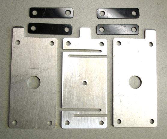
Most electronic weighing systems use load cells constructed from metal bars that bend or stretch very slightly and strain gauges to measure the deflections. Constructing a load cell from strain gauges is not very easy and the electronics involve sensitive (i.e. fussy) analog circuitry. This project was an attempt to build a different kind of load cell that I could construct without all the fuss. I involves a three-plate capacitor whose middle plate can move up and down in response to any weight pulling on it. I cut the capacitor plates from 1/16" 6061 T6 aluminum on my CNC mill. The center plate has some side cuts in it to make it deflect under less pressure than would otherwise be required to bend the whole thing. Here's a photo:

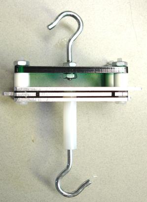
The plates were assembled with 1/32" Delrin spacers and nylon screws to insulate them from each other. I added a top plate made from acrylic and a couple hooks in order to measure force in tension (i.e. hanging weight). Here's a photo of the completed load cell:

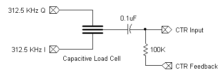
The outer plates of the load cell are driven by two 312.5 KHz square waves 90 degrees out of phase with each other. How much of each signal gets coupled to the center plate will depend on its relative closeness to the respective outer plate. To measure the deflection requires correlating the output with each of the two inputs and comparing the results. This is done by counters, in much the same way that my AM radio used them to detect signals. First, a counter is set up as if it were being used for sigma-delta ADC operation, except it doesn't need to count anything; we just need the inverted feedback. Next the I and Q counters are set up to output 312 KHz square waves 90 degrees out of phase with each other. Finally, two counters are set up in logic mode (XOR operation), each with the negative feedback as an input, along with either the I or Q output from the 312.5 KHz counters. Here's a schematic:

I borrowed some programming from the AM radio code and added what was needed specific to the weighing. The logic counters are allowed to count for one second, after which the increase in each phsx register is recorded. The ratio of one difference to the sum of both differences is what I use for the "weight" reading. The program I used is attached as an archive below.
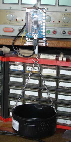
In order to test the load cell, I set it up as a hanging scale, suspended from the ceiling and using some chain and a pipe cap as a basket. I also attached the QuickStart board to the load cell in order to keep the leads short (very important, it turns out):

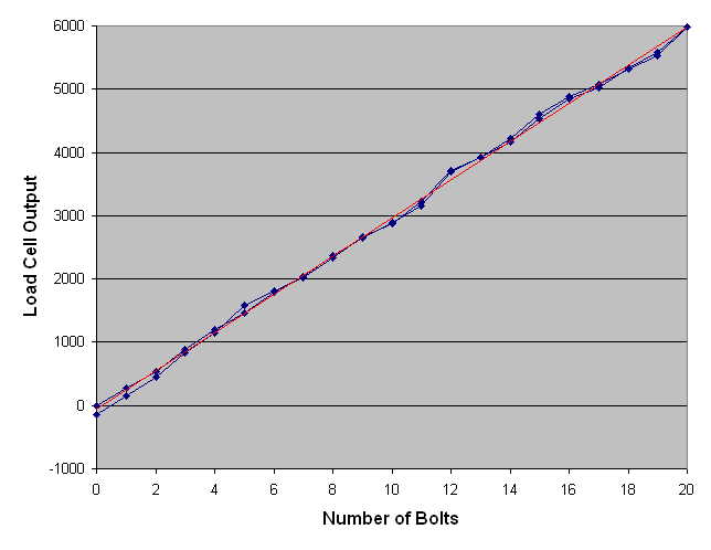
I got a bunch of bolts, each weighing about 11 grams to use as weights. I wanted to determine two things: 1) would I get a linear relationship between the actual weight and the readings, and 2) would there be any noticeable hysteresis, indicating that the center plate had "mechanical memory." So I did a tare, then added bolts to the basket one at a time, recording their weights, and then removed them one at a time, again recording weights. The results are plotted in Excel (blue), along with a linear trend line (red):

Although there are some bumps, the results didn't stray far from linearity. Also, there appears to be very little hysteresis, seeing as how the "outgoing" and "incoming" lines stay close together.
On the whole, I consider the experiment a success. Whether this technique has any practical value or not, I will leave for others to decide.
-Phil
The plates were assembled with 1/32" Delrin spacers and nylon screws to insulate them from each other. I added a top plate made from acrylic and a couple hooks in order to measure force in tension (i.e. hanging weight). Here's a photo of the completed load cell:
The outer plates of the load cell are driven by two 312.5 KHz square waves 90 degrees out of phase with each other. How much of each signal gets coupled to the center plate will depend on its relative closeness to the respective outer plate. To measure the deflection requires correlating the output with each of the two inputs and comparing the results. This is done by counters, in much the same way that my AM radio used them to detect signals. First, a counter is set up as if it were being used for sigma-delta ADC operation, except it doesn't need to count anything; we just need the inverted feedback. Next the I and Q counters are set up to output 312 KHz square waves 90 degrees out of phase with each other. Finally, two counters are set up in logic mode (XOR operation), each with the negative feedback as an input, along with either the I or Q output from the 312.5 KHz counters. Here's a schematic:
I borrowed some programming from the AM radio code and added what was needed specific to the weighing. The logic counters are allowed to count for one second, after which the increase in each phsx register is recorded. The ratio of one difference to the sum of both differences is what I use for the "weight" reading. The program I used is attached as an archive below.
In order to test the load cell, I set it up as a hanging scale, suspended from the ceiling and using some chain and a pipe cap as a basket. I also attached the QuickStart board to the load cell in order to keep the leads short (very important, it turns out):
I got a bunch of bolts, each weighing about 11 grams to use as weights. I wanted to determine two things: 1) would I get a linear relationship between the actual weight and the readings, and 2) would there be any noticeable hysteresis, indicating that the center plate had "mechanical memory." So I did a tare, then added bolts to the basket one at a time, recording their weights, and then removed them one at a time, again recording weights. The results are plotted in Excel (blue), along with a linear trend line (red):
Although there are some bumps, the results didn't stray far from linearity. Also, there appears to be very little hysteresis, seeing as how the "outgoing" and "incoming" lines stay close together.
On the whole, I consider the experiment a success. Whether this technique has any practical value or not, I will leave for others to decide.
-Phil



Comments
No really that's very cool ... I wonder what the results would be if you made your signals 180 Deg out of Phase rather than 90 Deg out of Phase. It's actually a similar circuit to the one I was using for the passive RFID reader.
You got me thinking though, reading the signal in quadrature versus differential might be more beneficial but very application dependent depending on what you were looking for in the signal to begin with.
This might get better differential action, if the centre plate was driven, and two 'capacitance sensor summers' run concurrently on the outer plates - that way you get close to simultaneous CAP readings.
A limit of this type of circuit, is the granularity of the RC sampling, which does not 'carry over' fractional bits and so you cannot get more precision with longer measuring times.
A non-sync excite frequency would help, but it would need to be stable.
Beau and jmg (who suggested a differential instead of a quadrature approach),
Quadrature is more robust, since the two signals are orthogonal to each other and their correlations are independent of one another. This means that I can separately extract each signal's contribution to the sum for comparison. By having both signals available indpendently, common mode effects, such as variance with temperature, noise, etc., can be canceled out. Were I to excite the top and bottom plates 180 degrees out of phase, the only data I would have available would be the difference between the two signals, with no clue about the total amplitude. jmg's idea about exciting the center and measuring on the outer plates may have some merit, since two signals are again available; but I doubt that it carries any advantages over the quadrature method. In fact, it might be worse, since two sigma-delta-style counters need to be set up, which potentially have different input characteristics.
-Phil
-Phil
Ken Gracey
Yes, I've been trying to decide what limits that.
One thing I can see that should be avoided, is the I/O clamp diodes, so that means a capacitive divider for the impulse drives - keep the signal just high enough to avoid the diodes.
Then, the Feedback resistor can determines the 'carry over' time constant. - So there may be a 'best value' for that ?
More accurate may be to call this residual Auto-Zero voltage a dither value, as that better describes how it improves precision.
Did you measure the plate capacitance, and get any waveforms. Drive in and RC 'spikes' out ?
A benefit of driving the outer plates from lower impedance is less pickup noise.
In My pencil sketches, suggest a phase-shifted impulse, would give better differential results than Quadrature.
I think the top option, interacts better with the XOR counter gate effect ?
BTW, "load cell" is a generic term that applies to any device that converts a force to an electrical signal. Most load cells in commercial application use multiple strain gauges in Wheastone bridge configurations, rather than capacitive effects. Here's an article that explains them better than I could:
I once had a Sears electronic bathroom scale that I disassembled to see what made it tick. The weighing platform sat upon multiple steel bars joined in an elaborate fulcrum configuration, each with a couple strain gauges attached. After going through the Wheatsone bridge and amplification via op amps the signal was fed to an RC timing setup using a General Instruments NMOS PIC controller. This was before Microchip acquired the PIC controller line. That was my first encounter with strain gauges.
BTW, it's much harder mechanically to design a scale that things sit on, compared to one that things hang from. In the latter case, it's simple to make sure that the applied force is normal to the sensor that measures it. In the former case, things like unbalanced loads and the torques they produce have to be considered.
-Phil
I'd expect that, as you are trying to measure fractional pF here, and adding more cables increases the un-changing portion, as well as much more 'aerial pickups'. Less separation between the plates (thinner spacers) should help too. Anything to make the change a larger percentage.
The P-P output from the center plate is about 2V, so there's no worry about involving the I/O clamp diodes.
-Phil
In your diagram,
there would be no advantage in using the top option. In the quadrature technique, contributions from I to Q simply cancel, and vice versa.
-Phil
I'm interested in those little deviations and what could possibly cause them, apart from those cheap bolts where they forget to slot the head properly (I'm sure that's not it!)
Couple of thoughts... if you made the middle (pickup) out of PCB you could implement a guard ring. Also are your "buckets" an even number of 312.5 khz cycles (probably) or are you dithering from bucket to bucket by having non-integer number of cycles? There are arguments both ways...
Obvious from the waveforms, I missed that the plates naturally act as a 50% voltage divider, so you have a 1/2 Vcc step, with no additional load.
It can't be the bolts, because I'm sure I did not put them in and take them out LIFO style. It might be from fine metal dust that I didn't get completely cleaned from the plates or even from scratches and dings in the metal. (As you can see from the photo, I did not bother to polish the plates.) Other than that, I cannot identify any possible sources of stiction that might contribute to the bumps, even though it does seem to be deterministic. It could also just be a matter of using a scale more suited for measuring pounds to measure ounces.
Yes, there are 312_500 cycles in each sample. Also, I picked 312.5 kHz since it divides 80 MHz by a power of two. So there are no issues with jitter in the I and Q signals, which would compromise the orthogonality of the two signals.
-Phil
The waveforms have given me a slight change, see below.
 Quadrature:
 T: ______/=========\__________/==========\________
BI: __________/==========\_________/===========\____
          TTzz       TTzz      TTzz        TTzz

Change to Phase shifted 2: T.H == B.L
 T: ______/=====\_______________/=====\___
 B: =================\_____/==============
                 TTzz      BBzz
TTzz is measure TT, then AutoZero phase, and
BBzz is measure B, then AutoZero phase
To me, the waveforms show it is not doing a truly balanced measurement, which should be one integrate cycle per active-capacitor to best null common mode variances like humidity effects.
If you look carefully you can see the Auto zero most clearly when T=L and B=H, and the measurement zones always follow a Top Edge.
The Bottom edges are indirectly measured, and then by a constant multiplier.(k*dB)
The modified Pulse will measure Top, then Bottom, in a mirror and alternating manner, and the Counter conditions would be
!T & FB -> Count During : TT + Tz + PWb + Bz
B & !FB -> Count During : BB + !Bz + PWt + !Tz
PWb = PWt, and Tz ~ !Tz, Bz ~ !Bz, keep zz times reasonably short.
It would be nice to avoid Tz, !Tz
The plate waveform will be very similar to what you show now.
I certainly wouldn't put one of those in the same category as a load cell. Last time I worked with an inclinometer it had all the electronics on the back of the transducer assembly, it required a clean 10 volt supply, I could almost crush it in my hands and the IP rating must have been 000!
this is a very interesting setup and experiment!
If you want to, you could explain a little bit more detailed, how the counter and software setup works. What I don't get is, what exactly is being counted or where exactly comes the step between analog and digital.
What do you estimate is the relative difference of the two capacities? Can you see or measure the deflection of the plate?
Thanks for sharing!
Christof
In order to separate the I and Q contributions to the signal, two additional counters are employed. Each has two inputs: either I or Q, and the feedback signal. The counters are set up to XOR their two inputs, which effectively correlates the pulse density on the feedback pin with the I and Q signals. Therefore the count on each counter after a given time interval will be proportional to the contribution of the selected I or Q component on the input pin.
I never measured the actual capacitance. I can see the center plate deflect, but there's too little room for fitting a caliper to measure the displacement.
-Phil
Perhaps you have seen my experiment:
http://forums.parallax.com/showthread.php?138702-A-Physics-Experiment-Measure-a-Force-or-a-Weight-with-the-Propeller
I am wondering, if your XOR-input counting could be used there somehow to find the resonance frequency of the wire faster, because the phase between the propeller output and the electro-mechanic system should be dependant from the relation of the two frequencies?
Christof
Another approach for eliminating noise would be to employ a phase-locked loop from the output of your op-amp to clean up the signal. It's effectiveness will depend on the range of frequencies you need to cover and the lock range of the PLL IC. Its advantage is that you can just count edges with the Prop, rather than having to search for a maximum response.
-Phil
Christof
Bruce
I tore apart a broken blood pressure monitor this morning and was looking at how it worked in particular what it used to measure the pressure. What I found is that it uses a 74HC02 quad nor gate to form an oscillator and between one of the stages of the oscillator there is a mechanical bellows attached to a round plate. The plate then changes its distance between it and another plate based on the amount of deflection from the bellows thus changing capacitance and frequency of the oscillator. Fairly simple.
I knew I had read somewhere on here about capacitive load cell or pressure sensing so I had to look.