

Stepper motor midband resonance compensation
 Peter Jakacki
Posts: 10,193
Peter Jakacki
Posts: 10,193
Arrgh... just typed up a long post on this subject and as I was entering the tags it just lost everything. I will try again (but briefly)
This post is mainly for those who have experience with midband resonance when running stepper motors at a certain speed and load etc. I am looking at driving the step clock directly on the L6470 and dithering it if I want to run in this speed range.
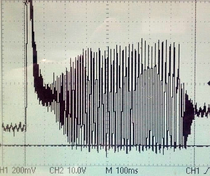
Looking at the first photo you can see what is happening with my NEMA34s at around about 150 RPM. The current peak is the motor start then it starts to ramp up to speed which in this case is in the problem range.Eventually the motor stalls
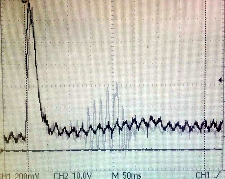
Here's a shot of one motor that works fine and another that doesn't (gray) when ramping through this range to a higher speed.
Seeing there are a few working with higher power motors (not talking about unipolar puppies) I'm wondering what you may have done to combat this problem other than using expensive drivers.
This post is mainly for those who have experience with midband resonance when running stepper motors at a certain speed and load etc. I am looking at driving the step clock directly on the L6470 and dithering it if I want to run in this speed range.
Looking at the first photo you can see what is happening with my NEMA34s at around about 150 RPM. The current peak is the motor start then it starts to ramp up to speed which in this case is in the problem range.Eventually the motor stalls
Here's a shot of one motor that works fine and another that doesn't (gray) when ramping through this range to a higher speed.
Seeing there are a few working with higher power motors (not talking about unipolar puppies) I'm wondering what you may have done to combat this problem other than using expensive drivers.

684 x 576 - 238K

726 x 580 - 229K
Comments
I don't have any traces to offer, what I did was run a motor through a current shunt with amplifier to read the ma the motor would draw. What I found was the locked rotor current was 250% of normal running current, and when a step was missed the current would spike even though I was chopping at the same rate. I would run up to 160% of normal current to overcome the resonance, past that it didn't help any.
Interestingly, this is all very similar to field weakening used in 3 phase induction motors. You have to pull the current back from saturation once you hit the knee point, so the speed will continue to climb. You could look at it like once you hit a certain RPM, you must derate the current from full saturation to weaken the field and overcome the back EMF.
BLDC controllers don't do field weakening, they just over voltage the motor, much like steppers are run. Run 400v into a 100v BLDC motor, but at reduced current so the effective power in the windings is the same. Then they only need to ramp the voltage up to max RPM, just like how induction motors are run up to base speed. At below base speed induction motors are run constant current, variable voltage, then above base speed they run variable current and constant voltage, to effect field weakening and overcome the back EMF so the RPMs will climb.
Just to to let you know that under proper load I don't really have a problem with resonance and the microstep really helps it to run quiet. I will post a video back on this thread showing what happens as I had a customer in disbelief that there was such a thing and that a motor could completely stall. But he saw it all with his own eyes.
1) Through software to change the rate through the resonant 'dead-band' and push through beyond, however it seems as thought you still hit the barrier somehow
2) Mechanically dampen the motor by changing the load characteristics through the barrier. This can be costly
3) Electronically insert a capacitive load across the stepper motor terminals during the barrier transition. This solution is cheap, and perhaps the most reliable. The idea, by inserting a capacitive load is to shift the resonant frequency to another location allowing the motor to traverse through the problematic speed region.
Can you clarify that ?
I was under the impression that microstepping helped avoid resonance effects as the magnetic vector rotated without jumps - or are you in a operating region where microstepping is not really happening ?
Does "under proper load" mean more torque, or more torque and a higher moment of inertia ?
have you tried your idea about the capacitor? I am curious, because I would assume, that you would need a rather big capacitor, because this is a mechanical oscillation with relatively low frequency.
Christof
"have you tried your idea about the capacitor?" - not my idea, just something that I read. I'll see if I can find a reference.
I couldn't find a particular reference, I just remember this from my motion control days in prosthetic research and development. The capacitor doen't need to be that big to skew the resonant frequency. The caveat is that you need to double up on your driver circuit, and when they are both running the gate drives need to be synchronized. Basically when both are running, you are 'inserting' a capacitor in parallel with the motor coils. Since the capacitor is trickle fed from the supply power, essentially you providing a current boost through the mid-range resonance region that can 'punch through' the barrier. At the same time the current boost quenches the resonant frequency buildup.
Note: The resistor and capacitor should be properly rated to handle your particular system.
I'm not following this line of logic ?
Any LC resonance will already be well outside the operating range, - the Stepper effects are Electro-Mechanical, not LCR in nature.
I can see that power phasing, and higher power supplies for more current-mode operation, can reduce L/R and improve dI/dT, but that is not an LCR effect.
I don't see how a cap is going to shift the resonance frequency, since that frequency is mechanical, not electrical.
-Phil